LTC3783EDHD#TRPBF Linear Technology, LTC3783EDHD#TRPBF Datasheet
LTC3783EDHD#TRPBF
Specifications of LTC3783EDHD#TRPBF
Available stocks


Related parts for LTC3783EDHD#TRPBF


LTC3783EDHD#TRPBF Summary of contents
Page 1
... Automotive Systems n 24V Industrial Controls n IP Phone Power Supplies , LT, LTC and LTM are registered trademarks of Linear Technology Corporation. True Color PWM and No R are trademarks of Linear Technology Corporation. SENSE All other trademarks are the property of their respective owners. TYPICAL APPLICATION ...
Page 2
... PLASTIC DFN = 125°C, θ 43°C/W JMAX JA EXPOSED PAD (PIN 17) IS GND, MUST BE SOLDERED TO PCB ORDER INFORMATION LEAD FREE FINISH TAPE AND REEL LTC3783EDHD#PBF LTC3783EDHD#TRPBF LTC3783IDHD#PBF LTC3783IDHD#TRPBF LTC3783EFE#PBF LTC3783EFE#TRPBF LTC3783IFE#PBF LTC3783IFE#TRPBF LEAD BASED FINISH TAPE AND REEL LTC3783EDHD LTC3783EDHD#TR ...
Page 3
ELECTRICAL CHARACTERISTICS range, otherwise specifi cations are T = 25° SYMBOL PARAMETER Main Control Loop/Whole System V Input Voltage Range IN I Input Voltage Supply Current Q Continuous Mode Shutdown Mode + V Rising RUN Input Threshold Voltage ...
Page 4
LTC3783 ELECTRICAL CHARACTERISTICS range, otherwise specifi cations are T = 25° SYMBOL PARAMETER R SYNC Input Pull-Down Resistance SYNC t Minimum On-Time ON(MIN) Low Dropout Regulator V INTV Regulator Output Voltage INTVCC CC UVLO INTV Undervoltage Lockout CC ...
Page 5
TYPICAL PERFORMANCE CHARACTERISTICS V vs Temperature REF 1.25 1.20 1.15 1.10 1.05 1.00 – 100 TEMPERATURE (°C) 3783 G01 I vs Temperature (PWMIN Low) Q 1.6 1.4 1.2 1.0 0.8 0.6 0.4 0.2 0 –75 – ...
Page 6
LTC3783 TYPICAL PERFORMANCE CHARACTERISTICS Frequency vs Temperature 350 340 330 320 310 300 290 280 270 260 250 – 100 TEMPERATURE (°C) 3783 G10 INTV Load Regulation CC 7.00 6.95 6.90 6.85 6.80 6.75 6.70 6.55 6.50 0 ...
Page 7
PIN FUNCTIONS FBN (Pin 1): Error Amplifi er Inverting Input/Negative Cur- rent Sense Pin. In voltage mode (V senses feedback voltage from either the external resistor divider across V for output voltage regulation, or the OUT grounded sense resistor under ...
Page 8
LTC3783 PIN FUNCTIONS I (Pin 15): Error Amplifi er Output/Compensation Pin. The TH current comparator input threshold increases with this control voltage, which is the output of the g Nominal voltage range for this pin 1.40V. RUN ...
Page 9
OPERATION Main Control Loop The LTC3783 is a constant frequency, current mode con- troller for PWM LED as well as DC/DC boost, SEPIC and fl yback converter applications. In constant current LED applications, the LTC3783 provides an especially wide PWM ...
Page 10
LTC3783 OPERATION The SS pin provides a soft-start current to charge an external capacitor. Enabled by RUN, the soft-start current is 50μA, which creates a positive voltage ramp which the internal I is limited, avoiding high peak ...
Page 11
OPERATION INTV Regulator Bypassing and Operation CC An internal, P-channel low dropout voltage regulator pro- duces the 7V supply which powers the gate drivers and logic circuitry within the LTC3783 as shown in Figure 3. The INTV regulator can supply ...
Page 12
LTC3783 OPERATION a maximum total gate charge of 35nC (the temperature coeffi cient of the gate charge is low 1.2mA + 35nC • 300kHz = 12mA Q(TOT 12V • 12mA = 144mW 70°C ...
Page 13
OPERATION For applications where the RUN pin is only to be used as a logic input, the user should be aware of the 7V Absolute Maximum Rating for this pin! The RUN pin can be con- nected to the input ...
Page 14
LTC3783 OPERATION Figure 6 illustrates these various quantities in relation to one another. Typically, in order to avoid visible fl icker, f greater than 120Hz. Assuming inductor and capacitor sizing which is close to discontinuous operation cycles are ...
Page 15
OPERATION Boost Converter: Inductor Selection Given an operating input voltage range, and having chosen the operating frequency and ripple current in the inductor, the inductor value can be determined using the following equation: ⎛ ⎞ MIN ( ) ...
Page 16
LTC3783 OPERATION During the switch on-time, the IMAX comparator limits the absolute maximum voltage drop across the power MOSFET to a nominal 150mV, regardless of duty cycle. The peak inductor current is therefore limited to 150mV/R The relationship between the ...
Page 17
OPERATION From a known power dissipated in the power MOSFET, its junction temperature can be obtained using the following formula: • θ FET JA The θ used in this equation normally ...
Page 18
LTC3783 OPERATION For many designs it is possible to choose a single capacitor type that satisfi es both the ESR and bulk C requirements for the design. In certain demanding applications, however, the ripple voltage can be improved signifi cantly ...
Page 19
OPERATION And so the inductor value is MIN ( ) = = L • D MAX Δ I • • 1 MHz should be: SENSE ...
Page 20
LTC3783 OPERATION 5. Check the stress on the power MOSFET by measuring its drain-to-source voltage directly across the device terminals (reference the ground of a single scope probe directly to the source pad on the PC board). Beware of inductive ...
Page 21
OPERATION Similar to the boost converter, which can be dimmed via the digital PWMIN input or the analog FBP pin, the buck- boost can be dimmed via the PWMIN pin or the analog I pin, which adjusts the offset voltage ...
Page 22
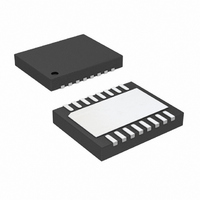
... TOP AND BOTTOM OF PACKAGE 22 Information furnished by Linear Technology Corporation is believed to be accurate and reliable. However, no responsibility is assumed for its use. Linear Technology Corporation makes no representa- tion that the interconnection of its circuits as described herein will not infringe on existing patent rights. DHD Package 16-Lead Plastic DFN (5mm × ...
Page 23
... DIMENSIONS ARE IN 3. DRAWING NOT TO SCALE Information furnished by Linear Technology Corporation is believed to be accurate and reliable. However, no responsibility is assumed for its use. Linear Technology Corporation makes no representa- tion that the interconnection of its circuits as described herein will not infringe on existing patent rights. FE Package 16-Lead Plastic TSSOP (4 ...
Page 24
... V www.linear.com ● ≤ 36V, 92% Duty Cycle IN ≤ 36V, 0.8V ≤ V ≤ 30V IN OUT ≤ 40V, 150kHz to 500kHz IN , 0.8V ≤ V ≤ 10V, 4V ≤ V ≤ 36V Q OUT IN ≤ 22V, 3 Hour Timer IN LT 0208 • PRINTED IN USA © LINEAR TECHNOLOGY CORPORATION 2008 3783fb ...