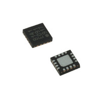
LDS8160-002-T2 IXYS, LDS8160-002-T2 Datasheet - Page 31

LDS8160-002-T2
Manufacturer Part Number
LDS8160-002-T2
Description
IC LED DVR WHT/RGB BCKLGT 16WQFN
Manufacturer
IXYS
Series
LED-Sense™, Power-Lite™r
Type
Backlight, White LED, RGB (I²C Interface)r
Datasheet
1.LDS8160-002-T2.pdf
(39 pages)
Specifications of LDS8160-002-T2
Topology
Linear (LDO), PWM
Number Of Outputs
6
Internal Driver
Yes
Type - Primary
Backlight
Type - Secondary
RGB, White LED
Frequency
1.2MHz
Voltage - Supply
2.3 V ~ 5.5 V
Mounting Type
Surface Mount
Package / Case
16-WQFN, 16-miniQFN
Operating Temperature
-40°C ~ 85°C
Current - Output / Channel
25mA
Internal Switch(s)
Yes
Efficiency
80%
Lead Free Status / RoHS Status
Lead free / RoHS Compliant
Voltage - Output
-
Lead Free Status / Rohs Status
Details
Other names
LDS8160-002-T2-2
LDS8160
Appendix 3
To implement the temperature correction of the I
vs. Temperature in respect to compensation curve,
the LED temperature should be known.
A very common and reliable method of measuring
temperature
advantage of the forward voltage (V
P-N junction semiconductor diode with respect to
temperature.
At any given current, the forward voltage (V
N junction diode is
Where:
= ideality factor; ~ 1 for silicon
k = Boltzmann constant = 1.38 x 10
q = Charge of electron = 1.602 x 10
T = Absolute Temperature, deg K
I
I
LEDs, based on compound semiconductors other
than silicon structures, have complex dependency
between forward voltage and current
Where
R
E
determines the wavelength of emitted light
h = 6.626 x 10
c = 3.0 x 10
= wavelength in m
The problem with measuring V
term is highly temperature dependent and very
difficult
generating a precise current that does not vary with
power supply, processing variations and temperature
is also very difficult.
Measuring V
and I
nature of logarithms, the difference, Δ V
two measurements will be linearly dependent on
temperature, and the I
the linear term is a function of a ratio of currents that
are relatively straightforward to implement and
independent of
temperature measurement method is also known as
© 2009 IXYS Corp.
Characteristics subject to change without notice
V
V
F
S
= the diode reverse saturation current, A.
S
g
F
F
= the diode forward current, A
– is LED series resistance, Ω ,
_
– is the bandgap energy of the material that
LED
(
F1
kT
q
allows avoiding these issues. Due to the
to
E
)
8
q
g
m/s - is the speed of light;
F
x
-34
in
measure
ln
at two separate forward currents, I
(Joules x s) - is Planck's constant;
kT
I
q
integrated
I
the operating conditions. This
F
S
ln
S
(1)
terms will cancel. In addition,
I
I
or
F
S
predict.
circuits
F
R
directly is that the I
S
LED TEMPERATURE MEASUREMENT
-23
-19
I
F
F
,
) behavior of a
coulombs
(Joules)/deg K
(2)
F
, between the
is
Additionally,
E
F
g
to
) of a P-
hc
take
LED
F2
,
S
31
the PTAT (proportional to absolute temperature)
technique, as the Δ V
(proportional) tracking coefficient with temperature.
A second method for diode temperature sensing
measures the diode V
(T
employed.
This is referred to as the CTAT (complementary to
absolute temperature) technique as the V
linear but negative (complementary) tracking rate
with temperature. This method requires that the V
temperature coefficient be pre-characterized.
The LDS8160 utilizes both techniques for improved
temperature estimation accuracy. A proprietary digital
arbitration algorithm resolves the final temperature
estimation every 2.5 seconds from both techniques
and a combination of on-chip silicon diode and LED
device measurements.
The ideality factor term, η , is based on the physic al
properties of the diode construction and directly
relates to the recombination leakage current caused
by defects. For an ideal diode = 1, and the V
increases at the rate of 60 mV per decade change in
I
therefore the change in V
decade change in I
This factor varies across manufactures and devices,
and it requires a calibration before direct temperature
sensing of the LEDs. The ideality factor may be
determined as the slope of the logarithmic I vs. V
diode characteristic in the low operating current
region (where effects of R
Series
characteristic. LEDs typically operate at forward
currents in the range of several of milliamps,
therefore, LEDs series resistance in the range of 10’s
of ohms results in a significant deviation from ideal
behavior. The actual R
the logarithmic I vs. V
current operating region.
Figure A3.1 shows a curve that represents a Nichia
WLED (NSSW020BT-P1) used for mobile display
backlighting. The R
is ~17 Ω and = ~ 1.55.
F
. Non-ideal P-N junctions (i.e. LEDs) have > 1;
1
V
F
and T
resistance,
2
kT
q
) at a constant I
ln
I
I
F
F
F
1
2
.
S
value extracted from this curve
F
F
R
F
S
curve of the diode in the high
at two different temperatures
S
R
value can be extracted from
has a linear and positive
S
,
S
F
are negligible).
Doc. No. 8160_DS, Rev. N1.0
, and it is also commonly
I
is
F
F
2
increases more per
another
I
F
1
(3)
non-ideal
F
has a
F
F


