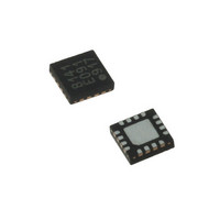
LDS8160-002-T2 IXYS, LDS8160-002-T2 Datasheet - Page 19

LDS8160-002-T2
Manufacturer Part Number
LDS8160-002-T2
Description
IC LED DVR WHT/RGB BCKLGT 16WQFN
Manufacturer
IXYS
Series
LED-Sense™, Power-Lite™r
Type
Backlight, White LED, RGB (I²C Interface)r
Datasheet
1.LDS8160-002-T2.pdf
(39 pages)
Specifications of LDS8160-002-T2
Topology
Linear (LDO), PWM
Number Of Outputs
6
Internal Driver
Yes
Type - Primary
Backlight
Type - Secondary
RGB, White LED
Frequency
1.2MHz
Voltage - Supply
2.3 V ~ 5.5 V
Mounting Type
Surface Mount
Package / Case
16-WQFN, 16-miniQFN
Operating Temperature
-40°C ~ 85°C
Current - Output / Channel
25mA
Internal Switch(s)
Yes
Efficiency
80%
Lead Free Status / RoHS Status
Lead free / RoHS Compliant
Voltage - Output
-
Lead Free Status / Rohs Status
Details
Other names
LDS8160-002-T2-2
LDS8160
Bit 0 of this register allows switching between
standard and low power standby modes (see
detailed description at “STANDBY MODE” section).
Bit 1 allows bypass soft start / ramp down if fast
raising/falling LED current required.
Bit 2 allows disable LED temperature compensation
if desired.
Bit 3 changes PWM generators start condition.
At normal operation mode, set by default, PWM
pulse rising edge of each PWM generator is shifted
by 120
decrease in input current noise especially at high
LED currents. However, it may be important for
better color mix in RGB mode to start all three PWM
pulses simultaneously. To do so, set register 1Eh
bit 3 = 1.
Bits 4, 5 are for factory use only.
The LDS8160 also provides the option for using an
external remote temperature-sensing device such
as a 2N3904. This option is available on channel
LEDA1 In this case, channel LEDA1 should be
disabled via register 03h and it cannot operate as a
LED current source.
A further option is available to monitor temperatures
and make adjustments only from sensing the on-
chip silicon diode temperature. This option is
enabled by setting bit 4 = 1 in register 1Eh. In this
mode, temperature correction is via LUTA only.
Bit 6 allows to change the PWM generators
operation mode from linear to logarithmic.
In Linear Mode, Dynamic Dimming resolution is ~
0.39% per LSB. Code 00h represents 100%
Dimming, while code FFh = 0%
Linear Dimming Mode recommended for WLED
Mode operation only because it creates non-
proportional Global Dimming in RGB Mode.
In Linear Dimming Mode, Dynamic Dimming
resolution is ~0.39% per LSB. Code 00h represents
100% Dimming, while Code FFh = 0% (See Figure
11).
Bit 7 allows switch between RGB and WLED
modes.
In RBG Mode, set by default, the LDS8160 uses
three independent PWM generators for LED current
dynamic dimming and three LUTs for independent
luminosity vs temperature correction. In WLED
Mode, the LDS8160 uses a single PWM generator
to dim all six LEDs and one LUT for luminosity vs
temperature correction. It is convenient if all six
WLED should have identical brightness. However, if
© 2009 IXYS Corp.
Characteristics subject to change without notice
0
in respect to two others. It allows for a
19
two or three different brightness levels are required for
LED banks A, B, and C using dynamic dimming, RGB
Mode is recommended even with WLED.
Figure 11: Global Dimming in Linear Mode in
percent vs. register 04h data
(0% dimming = full LED brightness)
STANDBY MODES
The LDS8160 has two standby modes, which
customers may set by I
1Fh with bit 6 = 1 (see Table 4).
In both standby modes, I
and all registers store information.
In Normal Standby Mode the LED drivers and internal
clock are off; however, some internal circuits remain
active resulting in a standby current from the V
source of 125 µA typical. In this mode, the EN pin
should be logic HIGH with signal level from 1.3 to V
voltage.
In Low Power (LP) Standby Mode most of the device is
disabled and results in very low standby current from
V
pin should be connected to a 1.8V voltage source
capable to provide up to ~100 µA maximum dynamic
current to LDS8160 digital core in case of any I
interface activity.. If this voltage source is unavailable,
Normal Standby Mode should be used.
To set LP Standby Mode, bit 0 in register 1Eh should
be set to 1 (see Table 2) before addressing to register
1Fh.
SHUTDOWN MODE
To set LDS8160 in shutdown mode, EN pin should be
logic low more than 10 ms. The LDS8160 shutdown
current is less than 1 µA. The LDS8160 wakes up from
shutdown mode with factory-preset data. To preserve
customer-programmed data, use either Normal or LP
standby modes.
IN
power source (5 µA typical). In LP Mode, the EN
2
C interface addressing register
2
C interface remains active
Doc. No. 8160_DS, Rev. N1.0
IN
power
2
C
IN


