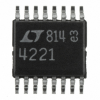
LTC4221CGN#PBF Linear Technology, LTC4221CGN#PBF Datasheet - Page 8

LTC4221CGN#PBF
Manufacturer Part Number
LTC4221CGN#PBF
Description
IC CTLR HOT SWAP DUAL 16SSOP
Manufacturer
Linear Technology
Type
Hot-Swap Controllerr
Datasheet
1.LTC4221CGNPBF.pdf
(28 pages)
Specifications of LTC4221CGN#PBF
Applications
General Purpose
Internal Switch(s)
No
Voltage - Supply
1 V ~ 13.5 V
Operating Temperature
0°C ~ 70°C
Mounting Type
Surface Mount
Package / Case
16-SSOP (0.150", 3.90mm Width)
Lead Free Status / RoHS Status
Lead free / RoHS Compliant
Available stocks
Company
Part Number
Manufacturer
Quantity
Price
PI FU CTIO S
LTC4221
ON1 (Pin 1): System/Channel 1 On Input. Both GATE pins
are pulled low by internal 100μA pull-downs and the
FAULT latch is reset when V
V
When V
timing cycle.
V
all the internal circuitry. V
for normal operation but it must be ≥V
age lockout circuit disables both channels whenever the
voltage at V
8
TYPICAL PERFOR A CE CHARACTERISTICS
ON1
CC1
0.500
0.450
0.400
0.350
0.300
0.250
0.200
0.150
0.100
0.050
–4.5
–3.1
–3.3
–3.7
–3.9
–4.1
–4.3
–3.5
U
0
–50
(Pin 2): Channel 1 Positive Supply Input. It powers
–50
< 0.821V, the FAULT latch is released from reset.
I
V
vs Temperature
FAULT(UP)
V
V
V
CC2
FAULT
PWRGD(OL)
CC2
ON1
–25
–25
U
= 1V
= 1V, I
V
V
V
= 1.5V
CC1
CC1
CC1
CC1
> 0.851V, GATE1 ramps up after an initial
0
= 2.7V
= 5V
= 13.5V
0
PWRGD
TEMPERATURE (°C)
TEMPERATURE (°C)
vs Temperature
is less than 2.5V.
/V
25
FAULT(OL)
25
/I
FAULT
U
50
50
= 1.6mA
CC1
75
75
V
V
V
W
CC1
CC1
CC1
can range from 2.7V to 13.5V
ON1
100
= 2.7V
= 5V
= 13.5V
100
4221 G34
4221 G37
< 0.4V. When 0.425V <
U
125
125
CC2
0.860
0.855
0.850
0.845
0.840
0.835
0.830
0.825
0.820
0.810
0.815
. An undervolt-
18
17
12
16
15
14
13
–50
0
V
tp
FAULT(TH)
V
TIMER = 0.5V
CC2
(SC-FAULT)
2
–25
= 1V
4
vs V
0
TEMPERATURE (°C)
vs Temperature
6
FALLING
CC1
V
RISING
25
CC1
8
SENSE1 (Pin 3): Channel 1 Current Sense Input. A sense
resistor R
and SENSE1 to sense channel 1 load current. If V
exceeds 100mV for more than 1μs or 25mV for an adjust-
able time (set by the C
fast pull-down circuits are triggered to discharge both
GATEs low. During the start-up cycle, GATE1 ramp-up is
controlled to servo V
increases from 9mV to 25mV as V
0.5V. To disable the current limit and circuit breaker
function for channel 1, tie SENSE1 to V
(V)
50
10
75
12
V
V
V
CC1
CC1
CC1
V
T
A
CC2
SENSE1
= 25°C
100
= 2.7V
= 5V
= 13.5V
14
= 1V
4221 G35
4221 G38
16
125
is placed in the supply path between V
RSENSE1
0.87
0.84
0.83
0.82
0.80
0.86
0.85
0.81
FILTER
0.6
1.8
1.6
1.4
1.2
1.0
0.8
–50
–50
V
tp
V
V
V
TIMER = 0.5V
FAULT(TH)
CC1
CC2
(FC-GATE)
CC2
–25
), the FAULT latch is set and
–25
= 5V
= 3.3V
= 1V
≤ V
SENSE(ACL)
0
0
vs Temperature
TEMPERATURE (°C)
TEMPERATURE (°C)
vs Temperature
FB1
25
25
ramps from 0V to
RISING
FALLING
CC1
50
50
.
. V
75
75
SENSE(ACL)
V
V
V
CC1
CC1
CC1
RSENSE1
100
100
= 2.7V
= 5V
= 13.5V
4221 G36
4221 G39
4221fa
CC1
125
125


