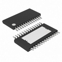
MAX7456EUI+ Maxim Integrated Products, MAX7456EUI+ Datasheet - Page 32

MAX7456EUI+
Manufacturer Part Number
MAX7456EUI+
Description
IC ON-SCREEN DISPLAY 28-TSSOP
Manufacturer
Maxim Integrated Products
Type
OSD (On-Screen Display) Video Generatorr
Datasheet
1.MAX7456EUI.pdf
(44 pages)
Specifications of MAX7456EUI+
Applications
Security Systems, Video Routing
Mounting Type
Surface Mount
Package / Case
28-TSSOP Exposed Pad, 28-eTSSOP, 28-HTSSOP
Current - Supply
58mA
Voltage - Supply
4.75 V ~ 5.25 V
Operating Temperature
-40°C ~ 85°C
Interface
SPI Serial
Display Type
OSD
Digits Or Characters
256 Characters
Maximum Clock Frequency
27 MHz
Operating Supply Voltage
5 V
Maximum Power Dissipation
2162 mW
Maximum Operating Temperature
+ 85 C
Maximum Supply Current
25 mA
Minimum Operating Temperature
- 40 C
Mounting Style
SMD/SMT
Lead Free Status / RoHS Status
Lead free / RoHS Compliant
Configuration
-
Lead Free Status / Rohs Status
Lead free / RoHS Compliant
Single-Channel Monochrome On-Screen
Display with Integrated EEPROM
Write address = 07H, read address = 87H.
Read/write access: unrestricted.
32
Display Memory Data In Register (DMDI)
BIT
7–0
______________________________________________________________________________________
DEFAULT
0000 0000
Character Address or Character Attribute byte to be stored in the display memory.
8-Bit Operation Mode (DMM[6] = 1)
If DMAH[1] = 0, the content is to be interpreted as a Character Address byte, where
If DMAH[1] = 1, the content is to be interpreted as a Character Attribute byte where
16-Bit Operation Mode (DMM[6] = 0)
The content is always interpreted as a Character Address byte where bits 7–0 =
CA[7:0] (Figure 12).
Auto-Increment Mode (DMM[0] = 1)
The character address CA[7:0] = FFH is reserved for use as an escape character that terminates
the auto-increment mode. Therefore, the character located at address FFH is not available for
writing to the display memory when in auto-increment mode. In all other modes, character FFH is
available.
Bits 7–0 = Character Address bits, CA[7:0] (Figure 12).
Bit 7 = Local Background Control bit, LBC (Figure 24 and Table 4)
Bit 6 = Blink bit, BLK
Bit 5 = Invert bit, INV (see Figure 24)
Bit 4–0 = 0
(The LBC, BLK, and INV bits are described in the Display Memory Mode register.)
To write to this register, the following condition must be
met:
DMM[2] = 0, the display memory is not in the process
of being cleared.
FUNCTION


