NCP1216AP100G ON Semiconductor, NCP1216AP100G Datasheet - Page 10
NCP1216AP100G
Manufacturer Part Number
NCP1216AP100G
Description
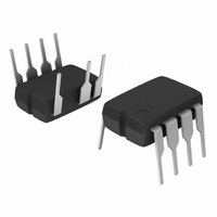
IC CTRLR PWM CM OTP HV 8DIP
Manufacturer
ON Semiconductor
Datasheet
1.NCP1216AP100G.pdf
(18 pages)
Specifications of NCP1216AP100G
Output Isolation
Isolated
Frequency Range
90 ~ 110kHz
Voltage - Input
10 ~ 16 V
Operating Temperature
0°C ~ 150°C
Package / Case
8-DIP (0.300", 7.62mm), 7 Leads
Duty Cycle (max)
50 %
Mounting Style
Through Hole
Switching Frequency
110 KHz
Maximum Operating Temperature
+ 150 C
Fall Time
20 ns
Rise Time
60 ns
Synchronous Pin
No
Topology
Flyback
Lead Free Status / RoHS Status
Lead free / RoHS Compliant
Available stocks
Company
Part Number
Manufacturer
Quantity
Price
Company:

Part Number:
NCP1216AP100G
Manufacturer:
ON Semiconductor
Quantity:
1 700
Part Number:
NCP1216AP100G
Manufacturer:
ON/安森美
Quantity:
20 000


Dynamic Self−Supply
V
can easily describe the current source operation with a bunch
of simple logical equations:
is ON, no output pulses
OFF, output is pulsing
ON, output is pulsing
offers the necessary light:
consumption and the MOSFET’s gate charge Q
select a 600 V 10 A MOSFET featuring a 30 nC Q
can compute the resulting average consumption supported
by the DSS which is:
The total IC heat dissipation incurred by the DSS only is
given by:
Suppose that we select the NCP1216P065 with the above
MOSFET, the total current is
Supplied from a 350 VDC rail (250 VAC), the heat
dissipated by the circuit would then be:
As you can see, it exists a tradeoff where the dissipation
capability of the NCP1216 fixes the maximum Q
circuit can drive, keeping its dissipation below a given
target. Please see the “Power Dissipation” section for a
complete design example and discover how a resistor can
help to heal the NCP1216 heat equation.
CC
I total [ F sw
I total
(30 n
350 V
The DSS principle is based on the charge/discharge of the
POWER−ON: If V
If V
If V
Typical values are: VCC
To better understand the operational principle, Figure 18
The DSS behavior actually depends on the internal IC
bulk capacitor from a low level up to a higher level. We
Figure 18. The Charge/Discharge Cycle Over a
CC
CC
V
10
ripple
decreasing > VCC
increasing < VCC
V pin8 .
65 k) ) 900 m + 2.9 mA.
2.9 mA + 1 W
= 2.2 V
ON, I = 8 mA
Q g ) I CC1 .
30
10 mF V
CC
< VCC
OFF
CC
OFF
50
ON
Capacitor
VCC
Output Pulse
OFF
= 12.2 V, VCC
then the Current Source is
then the Current Source is
VCC
OFF
then the Current Source
ON
OFF, I = 0 mA
70
= 12.2 V
= 10 V
ON
90
g
g
= 10 V
, then we
g
that the
. If we
http://onsemi.com
(eq. 1)
(eq. 2)
(eq. 3)
(eq. 4)
10
NCP1216 driving implementation, in particular for large Q
MOSFETs. This document can be downloaded at
www.onsemi.com/pub/Collateral/AND8069−D.PDF.
Ramp Compensation
sub−harmonic oscillations. These oscillations take place at
half the switching frequency and occur only during
Continuous Conduction Mode (CCM) with a duty−cycle
greater than 50%. To lower the current loop gain, one usually
injects between 50% and 100% of the inductor down−slope.
Figure 19 depicts how internally the ramp is generated:
a Duty cycle max at 75%. Over a 65 kHz frequency, it
corresponds to a
In our FLYBACK design, let’s suppose that our primary
inductance L
ratio of 1:0.1. The OFF time primary current slope is thus
given by:
when projected over an R
select 75% of the down−slope as the required amount of
ramp compensation, then we shall inject 27 mV/ms. Our
internal compensation being of 251 mV/ms, the divider ratio
(divratio) between R
of algebra to determine R
Frequency Jittering
signature by spreading the energy in the vicinity of the main
switching component. NCP1216 offers a $4% deviation of
0.75
V out ) V f
Application note AND8069/D details tricks to widen the
Ramp compensation is a known mean to cure
In the NCP1216, the ramp features a swing of 2.9 V with
19 k
Frequency jittering is a method used to soften the EMI
2.9
Figure 19. Inserting a Resistor in Series with the
1 * divratio
L p
Current Sense Information brings Ramp
65 kHz + 251 mV ms ramp.
divratio
+
−
From Set−point
p
is 350 mH, delivering 12 V with a Np : Ns
N p
N s
L.E.B
+ 2.37 kW
+ 371 mA ms or37 mV ms
comp
DC
Compensation
max
19 k
and the 19 kW is 0.107. A few lines
comp
sense
= 75°C
CS
:
of 0.1 W, for instance. If we
R
2.9V
comp
0V
R
sense
(eq. 5)
(eq. 6)
(eq. 7)
g
Related parts for NCP1216AP100G
Image
Part Number
Description
Manufacturer
Datasheet
Request
R

Part Number:
Description:
Pwm Current-mode Controller For High-power Universal Off-line Supplies
Manufacturer:
ON Semiconductor
Datasheet:
Part Number:
Description:
ON Semiconductor [VOLTAGE REGULATOR]
Manufacturer:
ON Semiconductor
Datasheet:
Part Number:
Description:
357-036-542-201 CARDEDGE 36POS DL .156 BLK LOPRO
Manufacturer:
ON Semiconductor
Datasheet:
Part Number:
Description:
357-036-542-201 CARDEDGE 36POS DL .156 BLK LOPRO
Manufacturer:
ON Semiconductor
Datasheet:
Part Number:
Description:
357-036-542-201 CARDEDGE 36POS DL .156 BLK LOPRO
Manufacturer:
ON Semiconductor
Datasheet:
Part Number:
Description:
357-036-542-201 CARDEDGE 36POS DL .156 BLK LOPRO
Manufacturer:
ON Semiconductor
Datasheet:
Part Number:
Description:
357-036-542-201 CARDEDGE 36POS DL .156 BLK LOPRO
Manufacturer:
ON Semiconductor
Datasheet:
Part Number:
Description:
357-036-542-201 CARDEDGE 36POS DL .156 BLK LOPRO
Manufacturer:
ON Semiconductor
Datasheet:
Part Number:
Description:
357-036-542-201 CARDEDGE 36POS DL .156 BLK LOPRO
Manufacturer:
ON Semiconductor
Datasheet:
Part Number:
Description:
357-036-542-201 CARDEDGE 36POS DL .156 BLK LOPRO
Manufacturer:
ON Semiconductor
Datasheet:
Part Number:
Description:
357-036-542-201 CARDEDGE 36POS DL .156 BLK LOPRO
Manufacturer:
ON Semiconductor
Datasheet:
Part Number:
Description:
357-036-542-201 CARDEDGE 36POS DL .156 BLK LOPRO
Manufacturer:
ON Semiconductor
Datasheet:
Part Number:
Description:
Manufacturer:
ON Semiconductor
Datasheet:
Part Number:
Description:
Manufacturer:
ON Semiconductor
Datasheet: