PKS607FN Power Integrations, PKS607FN Datasheet - Page 9
PKS607FN
Manufacturer Part Number
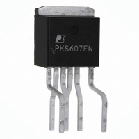
PKS607FN
Description
IC OFFLINE SWIT OTP OCP HV TO262
Manufacturer
Power Integrations
Series
PeakSwitch®r
Datasheet
1.PKS606PN.pdf
(24 pages)
Specifications of PKS607FN
Output Isolation
Isolated
Frequency Range
250 ~ 304kHz
Voltage - Output
700V
Power (watts)
126W
Operating Temperature
-40°C ~ 150°C
Package / Case
TO-262-7 (Formed Leads), 5 Leads
Input / Supply Voltage (max)
265 VAC
Input / Supply Voltage (min)
85 VAC
Duty Cycle (max)
68 %
Switching Frequency
277 kHz
Supply Current
1430 uA
Operating Temperature Range
- 40 C to + 150 C
Mounting Style
Through Hole
For Use With
596-1267 - KIT REF DESIGN PEAKSWITCH
Lead Free Status / RoHS Status
Lead free / RoHS Compliant
Other names
596-1140-5
Available stocks
Company
Part Number
Manufacturer
Quantity
Price
Company:

Part Number:
PKS607FN
Manufacturer:
POWER
Quantity:
15 000
Part Number:
PKS607FN
Manufacturer:
POWER
Quantity:
20 000


off the power supply. This protects the load and supply from
a continuous fault condition. Removing the AC input resets
this condition.
The output voltage is determined by the Zener diode VR2, the
voltage drop across R12 and the forward drop of D9 and the LED
of optocoupler U2. Resistor R13 provides bias current through
D9 and VR2, to ensure that VR2 is operating close to its knee
voltage, while R12 sets the overall gain of the feedback loop.
Capacitor C15 boosts high frequency loop gain to help distribute
the enabled switching cycles and reduce pulse grouping.
When the output voltage exceeds the feedback threshold voltage,
current will flow in the optocoupler LED, causing current flow in
the transistor of the optocoupler. W hen this exceeds the ENABLE
pin threshold current the next switching cycle is inhibited, as the
output voltage falls (below the feedback threshold) a conduction
cycle is allowed to occur and by adjusting the number of enabled
cycles output regulation is maintained. As the load reduces
the number of enabled cycles decreases, lowering the effective
switching frequency and scaling switching losses with load.
This provides almost constant efficiency down to very light
loads, ideal for meeting energy efficiency requirements.
PeakSwitch device U1 is supplied from an auxillary winding
on the transformer which is rectified and filtered by D7 and C6.
Resistor R7 provides approximately 2 mA of supply current into
the BYPASS pin capacitor C8. During startup or fault conditions
when the bias voltage is low, the BYPASS pin is supplied from
a high voltage current source within U1, eliminating the need
for separate startup components.
Components Q1-2, R9-11, R14, C13, C16, and VR3 form
an overvoltage and overcurrent protection circuit. An output
overvoltage or overcurrent condition fires SCR Q2, clamping
the output voltage and forcing PeakSwitch U1 into latching
shutdown after 30 ms. The low pass filter formed by R10 and
C13 adds a delay to the over-current sense. The shutdown
condition can be reset by briefly removing AC power for ~3
seconds (maximum). The latching function within PeakSwitch
significantly reduces the size of the SCR and output rectifier,
D8, as the short circuit current only flows for 50 ms before the
supply latches off.
This design meets EN55022 Class B conducted EMI with
>10 dB margin even with the output RTN directly connected
to earth ground.
Key Application Considerations
PeakSwitch Design Considerations
Output Power Table
The data sheet maximum output power table (Table 1) represents
the maximum practical continuous output power level that can
be obtained under the following assumed conditions:
1. The minimum DC input voltage is 100 V or higher for
2. Efficiency of 70% for Y/F packaged devices, 75% for P
3. Minimum datasheet value of I
4. Transformer primary inductance tolerance of ±10%
5. Reflected output voltage (V
6. Voltage only output of 15 V with an ultra fast PN rectifier
7. Continuous conduction mode operation with transient K
8. Sufficient heatsinking is provided, either externally (Y/F
9. Device ambient temperature of 50 °C for open frame designs
Peak vs. Continuous Power
PeakSwitch devices have current limit values that allow the
specified peak power values in the power table. With sufficient
heatsinking, these power levels could be provided continuously,
however this may not be practical in many applications.
PeakSwitch is optimized for use in applications that have short
duration, high peak power demand, but a significantly lower
continuous or average power. Typical ratios would be P
2 × P
a small core size to be selected to deliver the peak power,
but the short duration prevents the transformer winding from
overheating. A s average power increases, it may be necessary to
select a larger transformer to allow increased copper area for the
windings based on the measured transformer temperature.
The power table provides some guidance between peak
power and continuous power in sealed adapters, however
specific applications may differ. For example, if the peak
power condition is very low duty cycle, say a 2 second peak
occurring only at power up to accelerate a hard disk drive,
then the transformer’s thermal rise is only a function of the
continuous power. However, if the peak power occurs every
200 ms for 50 ms then it would need to be considered.
In all cases, the acceptable temperature rise of the PeakSwitch
and transformer should be verified under worst case ambient
and load conditions.
85 VAC input, or 220 V or higher for 230 VAC input or
single 100/115 VAC with a voltage doubler.
packaged devices at 85-265 VAC, 75% for 230 VAC input
all packages
diode
value of 0.25
packages) or through an area of PC board copper (P package)
to keep the SOURCE pin or tab temperature at or below
110 °C.
and 40 °C for sealed adapters
*Below a value of 1, K
current. To prevent reduced power capability due to premature
termination of switching cycles, a transient K
recommended. This avoids the initial current limit (I
exceeded at MOSFET turn on.
AVE
. The high switching frequency of PeakSwitch allows
P
is the ratio of ripple to peak primary
OR
PKS603-607
) of 135 V
2
f
P
limit of ≥0.25 is
INIT
Rev. I 02/07
) being
PEAK
P
≥
*
Related parts for PKS607FN
Image
Part Number
Description
Manufacturer
Datasheet
Request
R

Part Number:
Description:
SOP-16
Manufacturer:
Power Integrations
Datasheet:
Part Number:
Description:
DIP8
Manufacturer:
Power Integrations
Datasheet:
Part Number:
Description:
TO-263
Manufacturer:
Power Integrations
Datasheet:
Part Number:
Description:
TO-263
Manufacturer:
Power Integrations
Datasheet:
Part Number:
Description:
Manufacturer:
Power Integrations
Datasheet: