PKS607FN Power Integrations, PKS607FN Datasheet - Page 4
PKS607FN
Manufacturer Part Number
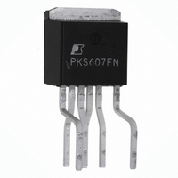
PKS607FN
Description
IC OFFLINE SWIT OTP OCP HV TO262
Manufacturer
Power Integrations
Series
PeakSwitch®r
Datasheet
1.PKS606PN.pdf
(24 pages)
Specifications of PKS607FN
Output Isolation
Isolated
Frequency Range
250 ~ 304kHz
Voltage - Output
700V
Power (watts)
126W
Operating Temperature
-40°C ~ 150°C
Package / Case
TO-262-7 (Formed Leads), 5 Leads
Input / Supply Voltage (max)
265 VAC
Input / Supply Voltage (min)
85 VAC
Duty Cycle (max)
68 %
Switching Frequency
277 kHz
Supply Current
1430 uA
Operating Temperature Range
- 40 C to + 150 C
Mounting Style
Through Hole
For Use With
596-1267 - KIT REF DESIGN PEAKSWITCH
Lead Free Status / RoHS Status
Lead free / RoHS Compliant
Other names
596-1140-5
Available stocks
Company
Part Number
Manufacturer
Quantity
Price
Company:

Part Number:
PKS607FN
Manufacturer:
POWER
Quantity:
15 000
Part Number:
PKS607FN
Manufacturer:
POWER
Quantity:
20 000


hysteresis of 75 °C (typical) is provided to prevent overheating
of the PC board during a continuous fault condition.
Current Limit
The current limit circuit senses the current in the power MOSFET.
When this current exceeds the internal threshold (I
power MOSFET is turned off for the remainder of that cycle. The
current limit state machine reduces the current limit threshold
by discrete amounts under medium and light loads.
The leading edge blanking circuit inhibits the current limit
comparator for a short time (t
turned on. This leading edge blanking time has been set so that
current spikes caused by capacitance and secondary-side rectifier
reverse recovery time will not cause premature termination of
the MOSFET conduction portion of the switching cycle.
During startup and fault conditions, the controller prevents
excessive drain currents by reducing the switching
frequency.
Adaptive Current Limit
When switching in the full current limit state, a skipped cycle
followed by a cycle that terminates at the full current limit
implies that the line voltage is at high line. Under this condition,
adaptive current limit reduces the full current limit level by
approximately 10% in order to reduce output overload power.
The next skipped cycle disables the adaptive current limit
condition and restores the full current limit level.
Line Under-Voltage Sense Circuit
The line under-voltage circuit prevents startup below the
programmed input voltage by connecting an external resistor
from either the DC line or from an AC sense circuit (see
Figure 1) to the EN/UV pin. The complete function is described
in the flow chart shown in Figure 5. During power up or when
the switching of the power MOSFET is disabled in auto-restart,
the current flowing into the EN/UV pin must exceed 25 µA to
initiate switching of the power MOSFET. During power up,
once the threshold is exceeded, the Bypass pin must charge from
4.8 V to 5.8 V before MOSFET switching is initiated.
The line under-voltage circuit also detects when there is no
external resistor connected to the EN/UV pin (less than ~1 µA
into pin). In this case, the line under-voltage function is disabled
and the device operates with a normal auto-restart function.
Programmable Smart AC Line Sense
When an external A C sense circuit is used (see Figure 1), the line
under-voltage sense circuit can be used to determine the reason
for a loss of feedback signal at the EN/UV pin. In the event of
a fault condition such as output overload, output short circuit,
or an open loop condition, the power MOSFET switching is
disabled after the EN/UV pin is not pulled low for 30 ms. If the
AC line is present (I
Rev. I 02/07
PKS603-607
EN
> 25 µA) at the time switching is disabled,
LEB
) after the power MOSFET is
LIMIT
), the
Figure 5. PeakSwitch Line Sense Function Flow Chart.
Yes
No
No
4. Start Switching
8. Reset A/R Latch
6. Stop Switching
2. UV Resistor
5. No Feedback
Yes
3. AC Input
7. AC Input
(I
(I
Yes
Yes
1. Startup
Present?
Present?
Present?
EN
>30 ms?
EN
No
>25 µA)
>25 µA)
No
Note: Normal operation
(no fault present) is denoted
by looping with a “No” response
at decision box 5 or 10.
11. Stop Switching
9. Start Switching
10. No Feedback
>30 ms?
(for 5 s)
Yes
PI-4014-062305
No
Related parts for PKS607FN
Image
Part Number
Description
Manufacturer
Datasheet
Request
R

Part Number:
Description:
SOP-16
Manufacturer:
Power Integrations
Datasheet:
Part Number:
Description:
DIP8
Manufacturer:
Power Integrations
Datasheet:
Part Number:
Description:
TO-263
Manufacturer:
Power Integrations
Datasheet:
Part Number:
Description:
TO-263
Manufacturer:
Power Integrations
Datasheet:
Part Number:
Description:
Manufacturer:
Power Integrations
Datasheet: