DS28EC20+ Maxim Integrated Products, DS28EC20+ Datasheet - Page 16
DS28EC20+
Manufacturer Part Number
DS28EC20+
Description
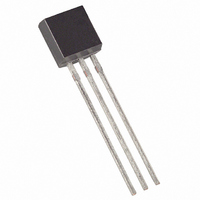
IC EEPROM 20KBIT TO92-3
Manufacturer
Maxim Integrated Products
Datasheet
1.DS28EC20PT.pdf
(27 pages)
Specifications of DS28EC20+
Format - Memory
EEPROMs - Serial
Memory Type
EEPROM
Memory Size
20K (256 x 80)
Interface
1-Wire Serial
Operating Temperature
-40°C ~ 85°C
Package / Case
TO-92-3 (Standard Body), TO-226
Lead Free Status / RoHS Status
Lead free / RoHS Compliant
Voltage - Supply
-
Speed
-


DS28EC20: 20Kb 1-Wire EEPROM
COPY SCRATCHPAD [55h]
The Copy Scratchpad command is used to copy data from the scratchpad to the data memory and the writable
sections of the register page. After issuing the Copy Scratchpad command, the master must provide a 3-byte
authorization pattern, which should have been obtained by an immediately preceding Read Scratchpad command.
This 3-byte pattern must exactly match the data contained in the three address registers (TA1, TA2, E/S, in that
order). If the pattern matches, the target address is valid, the PF and BS flag are not set, and the target memory is
not copy protected, the AA flag is set and the copy begins. The data to be copied is determined by the three
address registers. The scratchpad data from the beginning offset through the ending offset is copied to memory,
starting at the target address. Anywhere from 1 to 32 bytes can be copied with this command. The duration of the
device’s internal data transfer is t
during which the 1-Wire bus must be idle or actively pulled high. Active
PROG
pullup is optional for this device. A pattern of alternating 0s and 1s are transmitted after the data has been copied
until the master issues a reset pulse. If the PF flag or BS flag is set or the target memory is copy protected, the
copy does not begin and the AA flag is not set. The BS flag ensures that Copy Scratchpad is not executed
(blocked) if there was a Read Memory or Extended Read Memory between Write Scratchpad and Copy
Scratchpad.
READ MEMORY [F0h]
The Read Memory command is the general function to read from the DS28EC20. After issuing the command, the
master must provide a 2-byte target address, which should be in the range of 0000h to 0A3Fh. If the target address
is higher than 0A3Fh, the DS28EC20 changes the upper four address bits to 0. After the address is transmitted, the
master reads data starting at the (modified) target address and can continue until address 0A3Fh. If the master
continues reading, the result is FFh. The Read Memory command sequence can be ended at any point by issuing
a reset pulse. Note that the target address provided with the Read Memory flow overwrites the target address that
was specified with a previously issued Write Scratchpad command. Since the command also sets the BS flag, a
subsequent Copy Scratchpad command fails even if the authorization pattern matches.
EXTENDED READ MEMORY [A5h]
This command works essentially the same way as Read Memory, except for the 16-bit CRC that the DS28EC20
generates and transmits following the last data byte of a memory page. The CRC generated by this command uses
the same polynomial as the Write Scratchpad command. After issuing the command, the master must provide a 2-
byte target address, which should be in the range of 0000h to 0A3Fh. If the target address is higher than 0A3Fh,
the DS28EC20 changes the upper four address bits to 0. After the address is transmitted, the master reads data
starting at the (modified) target address and continuing until the end of a 32-byte page is reached. At that point the
bus master receives an inverted 16-bit CRC. If the master continues reading it receives data starting at the begin-
ning of the next page, followed again by the inverted CRC for that page. Reading beyond the end of the memory is
permissible, but the result is FFh. The Extended Read Memory command sequence can be ended at any point by
issuing a reset pulse. Note that the target address provided with the Extended Read Memory flow overwrites the
target address that was specified with a previously issued Write Scratchpad command. Since the command also
sets the BS flag, a subsequent Copy Scratchpad command fails even if the authorization pattern matches.
1-Wire BUS SYSTEM
The 1-Wire bus is a system that has a single bus master and one or more slaves. In all instances the DS28EC20 is
a slave device. The bus master is typically a microcontroller. The discussion of this bus system is broken down into
three topics: hardware configuration, transaction sequence, and 1-Wire signaling (signal types and timing). The
1-Wire protocol defines bus transactions in terms of the bus state during specific time slots, which are initiated on
the falling edge of sync pulses from the bus master.
HARDWARE CONFIGURATION
The 1-Wire bus has only a single line by definition; it is important that each device on the bus be able to drive it at
the appropriate time. To facilitate this, each device attached to the 1-Wire bus must have open-drain or tri-state
outputs. The 1-Wire port of the DS28EC20 is open drain with an internal circuit equivalent to that shown in
Figure 8.
16 of 27
Related parts for DS28EC20+
Image
Part Number
Description
Manufacturer
Datasheet
Request
R

Part Number:
Description:
MAX7528KCWPMaxim Integrated Products [CMOS Dual 8-Bit Buffered Multiplying DACs]
Manufacturer:
Maxim Integrated Products
Datasheet:
Part Number:
Description:
Single +5V, fully integrated, 1.25Gbps laser diode driver.
Manufacturer:
Maxim Integrated Products
Datasheet:
Part Number:
Description:
Single +5V, fully integrated, 155Mbps laser diode driver.
Manufacturer:
Maxim Integrated Products
Datasheet:
Part Number:
Description:
VRD11/VRD10, K8 Rev F 2/3/4-Phase PWM Controllers with Integrated Dual MOSFET Drivers
Manufacturer:
Maxim Integrated Products
Datasheet:
Part Number:
Description:
Highly Integrated Level 2 SMBus Battery Chargers
Manufacturer:
Maxim Integrated Products
Datasheet:
Part Number:
Description:
Current Monitor and Accumulator with Integrated Sense Resistor; ; Temperature Range: -40°C to +85°C
Manufacturer:
Maxim Integrated Products
Part Number:
Description:
TSSOP 14/A�/RS-485 Transceivers with Integrated 100O/120O Termination Resis
Manufacturer:
Maxim Integrated Products
Part Number:
Description:
TSSOP 14/A�/RS-485 Transceivers with Integrated 100O/120O Termination Resis
Manufacturer:
Maxim Integrated Products
Part Number:
Description:
QFN 16/A�/AC-DC and DC-DC Peak-Current-Mode Converters with Integrated Step
Manufacturer:
Maxim Integrated Products
Part Number:
Description:
TDFN/A/65V, 1A, 600KHZ, SYNCHRONOUS STEP-DOWN REGULATOR WITH INTEGRATED SWI
Manufacturer:
Maxim Integrated Products
Part Number:
Description:
Integrated Temperature Controller f
Manufacturer:
Maxim Integrated Products
Part Number:
Description:
SOT23-6/I�/45MHz to 650MHz, Integrated IF VCOs with Differential Output
Manufacturer:
Maxim Integrated Products
Part Number:
Description:
SOT23-6/I�/45MHz to 650MHz, Integrated IF VCOs with Differential Output
Manufacturer:
Maxim Integrated Products
Part Number:
Description:
EVALUATION KIT/2.4GHZ TO 2.5GHZ 802.11G/B RF TRANSCEIVER WITH INTEGRATED PA
Manufacturer:
Maxim Integrated Products
Part Number:
Description:
QFN/E/DUAL PCIE/SATA HIGH SPEED SWITCH WITH INTEGRATED BIAS RESISTOR
Manufacturer:
Maxim Integrated Products
Datasheet: