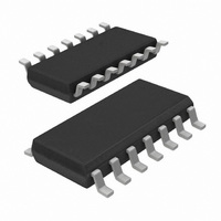
74HC125D,653 NXP Semiconductors, 74HC125D,653 Datasheet - Page 16

74HC125D,653
Manufacturer Part Number
74HC125D,653
Description
IC BUFFER DVR TRI-ST QD 14SOICN
Manufacturer
NXP Semiconductors
Series
74HCr
Datasheets
1.74HCT4046ADB112.pdf
(19 pages)
2.74HCT4046ADB112.pdf
(23 pages)
3.74HCT125D653.pdf
(6 pages)
Specifications of 74HC125D,653
Logic Type
Buffer/Line Driver, Non-Inverting
Package / Case
14-SOIC (3.9mm Width), 14-SOL
Number Of Elements
4
Number Of Bits Per Element
1
Current - Output High, Low
7.8mA, 7.8mA
Voltage - Supply
2 V ~ 6 V
Mounting Type
Surface Mount
Logic Family
74HC
Number Of Channels Per Chip
4
Polarity
Non-Inverting
Supply Voltage (max)
6 V
Supply Voltage (min)
2 V
Maximum Operating Temperature
125 C
Mounting Style
SMD/SMT
High Level Output Current
- 7.8 mA
Input Bias Current (max)
8 uA
Low Level Output Current
7.8 mA
Maximum Power Dissipation
500 mW
Minimum Operating Temperature
- 40 C
Number Of Lines (input / Output)
8 / 4
Output Type
3-State
Propagation Delay Time
9 ns
Lead Free Status / RoHS Status
Lead free / RoHS Compliant
Operating Temperature
-
Lead Free Status / Rohs Status
Lead free / RoHS Compliant
Other names
568-1392-2
74HC125D-T
933756990653
74HC125D-T
933756990653
Available stocks
Company
Part Number
Manufacturer
Quantity
Price
Part Number:
74HC125D,653
Manufacturer:
NXP/恩智浦
Quantity:
20 000
Philips Semiconductors
HCMOS family characteristics
FAMILY SPECIFICATIONS
AC CHARACTERISTICS
The “AC CHARACTERISTICS” table lists the guaranteed
limits when a device is tested under the conditions given in
the AC Test Circuits and Waveforms section.
TEST CIRCUITS
Good high-frequency wiring practices should be used in
test circuits. Capacitor leads should be as short as
possible to minimize ripples on the output waveform
transitions and undershoot. Generous ground metal
(preferably a ground-plane) should be used for the same
reasons. A V
decoupling capacitor should be provided
CC
at the test socket, also with short leads. Input signals
should have rise and fall times of 6 ns, a signal swing of
0 V to V
for 74HC and 0 V to 3 V for 74HCT; a 1.0 MHz
CC
square wave is recommended for most propagation delay
tests. The repetition rate must be increased for testing
f
. Two pulse generators are usually required for testing
max
such parameters as set-up time, hold time and removal
time. f
is also tested with 6 ns input rise and fall times,
max
with a 50% duty factor, but for typical f
as high as
max
60 MHz, there are no constraints on rise and fall times.
March 1988
16


