LMH1983SQE/NOPB National Semiconductor, LMH1983SQE/NOPB Datasheet - Page 31

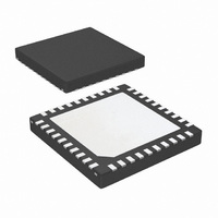
LMH1983SQE/NOPB
Manufacturer Part Number
LMH1983SQE/NOPB
Description
IC VID CLK GEN MULTI RATE 40LLP
Manufacturer
National Semiconductor
Type
Clock Generatorr
Datasheet
1.LMH1983SQENOPB.pdf
(38 pages)
Specifications of LMH1983SQE/NOPB
Applications
Video Equipment
Mounting Type
Surface Mount
Package / Case
40-LLP
Leaded Process Compatible
Yes
Rohs Compliant
Yes
Interface Type
I2C
Supply Voltage (max)
3.3 V
Maximum Operating Temperature
+ 85 C
Minimum Operating Temperature
- 40 C
Mounting Style
SMD/SMT
Peak Reflow Compatible (260 C)
Yes
Lead Free Status / RoHS Status
Lead free / RoHS Compliant
Other names
LMH1983SQETR
Available stocks
Company
Part Number
Manufacturer
Quantity
Price
Part Number:
LMH1983SQE/NOPB
Manufacturer:
TI/德州仪器
Quantity:
20 000
Output Driver Adjustments
The LVDS output drivers can be adjusted via the I
to change the differential output voltage swing, the common
mode voltage and to apply pre-emphasis to the LVDS output
Register 0x3A MSB (bit 7) turns on the pre-emphasis which
may be used to extend the reach between the LMH1983 and
the load. It is recommended that the trace length be kept
short, as longer traces have more opportunity to couple with
hostile signals and degrade jitter performance.
The differential output swing of CLKout pins is adjusted
through bits [6:4] of register 0x3A a larger value loaded into
this portion of the register will increase the output swing.
The common mode output voltage is also able to be adjusted
via register 0x3A, using register bits [3:0]
TOF1 Alignment
Each of the four clock outputs has a corresponding Top Of
Frame (TOF) output signal. The LMH1983 is programmed
with a video format for each of the three video clocks, and the
TOF signal will provide a digital indication of when the start of
a new frame occurs for that particular format. As an example,
if PLL1 is programmed with a video format corresponding to
NTSC, CLK1 will be 27 MHz, and TOF1 will output a pulse
once per frame, or once every 900,900 clock cycles. The de-
fault state is for the LMH1983 to detect the input reference
format, and to program this format as the output format for
CLK1, so if the input reference is an NTSC reference, then
TOF1 will default to a 29.97 Hz signal.
If the H
the LMH1981 Sync Separator, then the rising edge of the
F
The TOF pulse, if aligned, will be a pulse with a width of 1 H
period, with transitions aligned with the leading edges of the
H
H period in which the F
the “TOF1 Timing” scope shot.
IN
IN
input will come in the middle of a line (between H
pulses, and when set for a 0 offset, will be high during the
IN
, V
IN
, and F
Horizontal scale: 7 ps / div
CLKout4 Jitter Histogram
IN
inputs to the LMH1983 are coming from
IN
input transitions, as can be seed in
2
C interface
IN
30085158
pulses.
31
The alignment between the incoming F
may be controlled in a number of ways. There are three dif-
ferent alignment modes in which TOF1 may operate, selected
via register 0x11h. The default, powerup mode is for there to
be no alignment, the other two options are to always force
alignment to F
misaligned. Misalignment can be defined by the user via reg-
ister 0x15h where a window is defined which specifies the
amount of mismatch that is permitted between F
while still considering them to be aligned. If the input reference
signal has a significant amount of low frequency jitter or wan-
der, it may be possible for the relative alignment between
TOF1 and F
its jitter and wander attenuated by the PLL1 loop filter. If the
align always mode is selected, this may lead to timing jumps
on the output of CLKout1/TOF1 which would be undesirable.
Once the device decides that it needs to align TOF1 and
F
volves simply resetting the counter which keeps track of
where the TOF1 output transition happens, and results in an
instantaneous shift of TOF1 to align with F
volves using the second loop in PLL1, and skewing the VCXO
to make the frequency of CLKout1 either speed up or slow
down, slowly pulling TOF1 and F
reference is applied, which is not in alignment with TOF1, but
the output is currently in use, it may be better to slew TOF1
into alignment rather than to cause a major disruption in the
timing with a crash lock. The LMH1983 allows the user to se-
lect either crash lock, or drift lock under each of two different
conditions, controllable via register 0x11h. If the difference in
phase between TOF1 and F
IN
, there are two ways that it can be done. Crash lock in-
IN
to move around since the TOF1 output will have
IN
, and to force alignment to F
CLKout4 Phase Noise
TOF1 Timing
in
is small, and if the difference
IN
into alignment. If a new
IN
and the TOF1 output
IN
IN
when they are
. Drift lock in-
IN
www.national.com
and TOF1
30085154
30085150


