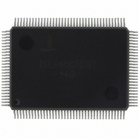
ISL98001CQZ-140 Intersil, ISL98001CQZ-140 Datasheet - Page 22

ISL98001CQZ-140
Manufacturer Part Number
ISL98001CQZ-140
Description
IC TRPL VIDEO DIGITIZER 128-MQFP
Manufacturer
Intersil
Type
Video Digitizerr
Datasheet
1.ISL98001IQZ-140.pdf
(31 pages)
Specifications of ISL98001CQZ-140
Applications
Digital TV, Displays, Digital KVM, Graphics Processing
Mounting Type
Surface Mount
Package / Case
128-MQFP, 128-PQFP
Rohs Compliant
Yes
Lead Free Status / RoHS Status
Lead free / RoHS Compliant
Available stocks
Company
Part Number
Manufacturer
Quantity
Price
Company:
Part Number:
ISL98001CQZ-140
Manufacturer:
Intersil
Quantity:
457
Part Number:
ISL98001CQZ-140
Manufacturer:
INTERSIL
Quantity:
20 000
PGA
The ISL98001’s Programmable Gain Amplifier (PGA) has a
nominal gain range from 0.5V/V (-6dB) to 2.0V/V (+6dB).
The transfer function is in Equation 1:
where GainCode is the value in the Gain register for that
particular color. Note that for a gain of 1V/V, the GainCode
should be 85 (0x55). This is a different center value than the
128 (0x80) value used by some other AFEs, so the firmware
should take this into account when adjusting gains.
The PGAs are updated by the internal clamp signal once per
line. In normal operation this means that there is a maximum
delay of one HSYNC period between a write to a Gain
register for a particular color and the corresponding change
in that channel’s actual PGA gain. If there is no regular
HSYNC/SOG source, or if the external clamp option is
enabled (register 0x13[5:4]) but there is no external clamp
signal being generated, it may take up to 100ms for a write
to the Gain register to update the PGA. This is not an issue
in normal operation with RGB and YPbPr signals.
Bandwidth and Peaking Control
Register 0x0D[3:1] controls a low pass filter allowing the
input bandwidth to be adjusted with three bit resolution
between its default value (0x0E = 780MHz) and its minimum
bandwidth (0x00, for 100MHz). Typically the higher the
resolution, the higher the desired input bandwidth. To
minimize noise, video signals should be digitized with the
minimum bandwidth setting that passes sharp edges.
Table 4 shows the corner frequencies for different register
settings.
Register 0x0D[7:4] controls a programmable zero, allowing
high frequencies to be boosted, restoring some of the
harmonics lost due to excessive EMI filtering, cable losses, etc.
This control has a very large range, and can introduce high
frequency noise into the image, so it should be used judiciously,
or as an advanced user adjustment.
Gain
(LSB = “x” = “don’t care”)
⎛ ⎞
⎝ ⎠
V
--- -
V
0x0D[3:0] VALUE
=
0.5
000x
001x
010x
100x
101x
011x
110x
111x
TABLE 4. BANDWIDTH CONTROL
+
GainCode
---------------------------- -
170
22
AFE BANDWIDTH
100MHz
130MHz
150MHz
180MHz
230MHz
320MHz
480MHz
780MHz
(EQ. 1)
ISL98001
Table 5 shows the corner frequency of the zero for different
peaking register settings. Values above 0x2 may cause
excessive noise, depending on the quality of the input signal
and the PCB environment.
Offset DAC
The ISL98001 features a 10-bit Digital-to-Analog Converter
(DAC) to provide extremely fine control over the full channel
offset. The DAC is placed after the PGA to eliminate
interaction between the PGA (controlling “contrast”) and the
Offset DAC (controlling “brightness”).
In normal operation, the Offset DAC is controlled by the
ABLC circuit, ensuring that the offset is always reduced to
sub-LSB levels (See“Automatic Black Level Compensation
(ABLC™)” on page 23). When ABLC is enabled, the Offset
registers (0x09, 0x0A, 0x0B) control a digital offset added
to or subtracted from the output of the ADC. This mode
provides the best image quality and eliminates the need for
any offset calibration.
If desired, ABLC can be disabled (0x17[0] = 1) and the
Offset DAC programmed manually, with the 8 most
0X0D[7:4] VALUE
TABLE 5. PEAKING CORNER FREQUENCIES
0xC
0xD
0xA
0xB
0xE
0xF
0x0
0x1
0x2
0x3
0x4
0x5
0x6
0x7
0x8
0x9
ZERO CORNER FREQUENCY
Peaking disabled
800MHz
400MHz
265MHz
200MHz
160MHz
135MHz
115MHz
100MHz
80MHz
70MHz
55MHz
50MHz
90MHz
65MHz
60MHz
September 21, 2010
FN6148.5


