ISL98001CQZ-140 Intersil, ISL98001CQZ-140 Datasheet - Page 16
ISL98001CQZ-140
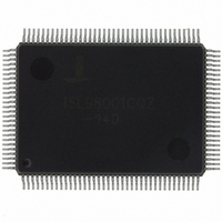
Manufacturer Part Number
ISL98001CQZ-140
Description
IC TRPL VIDEO DIGITIZER 128-MQFP
Manufacturer
Intersil
Type
Video Digitizerr
Datasheet
1.ISL98001IQZ-140.pdf
(31 pages)
Specifications of ISL98001CQZ-140
Applications
Digital TV, Displays, Digital KVM, Graphics Processing
Mounting Type
Surface Mount
Package / Case
128-MQFP, 128-PQFP
Rohs Compliant
Yes
Lead Free Status / RoHS Status
Lead free / RoHS Compliant
Available stocks
Company
Part Number
Manufacturer
Quantity
Price
Company:

Part Number:
ISL98001CQZ-140
Manufacturer:
Intersil
Quantity:
457
Part Number:
ISL98001CQZ-140
Manufacturer:
INTERSIL
Quantity:
20 000


Register Listing
0x18
0x19
0x1A
0x1B
0x1C
ADDRESS
Output Format (0x00)
HS
Output Signal Disable (0x00)
Power Control (0x00)
PLL Tuning (0x49)
OUT
REGISTER (DEFAULT VALUE)
Width (0x10)
(Continued)
16
BIT(S)
7:0
7:4
7:0
0
1
2
3
4
5
6
7
0
1
2
3
4
5
6
7
0
1
2
3
ISL98001
Bus Width
Interleaving
(48-bit mode only)
Bus Swap
(48-bit mode only)
UV order
(422 mode only)
422 mode
DATACLK
Polarity
VS
HS
HS
Three-state R
Three-state R
Three-state G
Three-state G
Three-state B
Three-state B
Three-state
DATACLK
Three-state
DATACLK
Red
Power-down
Green
Power-down
Blue
Power-down
PLL
Power-down
Reserved
Reserved
FUNCTION NAME
OUT
OUT
OUT
Polarity
Polarity
Width
P
S
P
S
P
S
[7:0]
7:0]
[7:0]
[7:0]
[7:0]
7:0]
0: 24-bits: Data output on R
are all driven low (default).
1: 48-bits: Data output on R
0: No interleaving: data changes on same edge of
DATACLK (default).
1: Interleaved: Secondary databus data changes on
opposite edge of DATACLK from primary databus.
0: First data byte after trailing edge of HSOUT
appears on R
1: First data byte after trailing edge of HSOUT
appears on R
busses are reversed).
0: U0 V0 U2 V2 U4 V4 U6 V6… (default)
1: U0 V1 U2 V3 U4 V5 U6 V7… (X980xx)
0: Data is formatted as 4:4:4 (RGB, default).
1: Data is decimated to 4:2:2 (YUV), blue channel is
driven low.
0: HS
edge of DATACLK (default).
1: HS
edge of DATACLK.
0: Active High (default)
1: Active Low
0: Active High (default)
1: Active Low
HS
bit modes, 0x02 for 48-bit modes.
0 = Output byte enabled
1 = Output byte three-stated
These bits override all other I/O settings
Output data pins have 56kΩ pulldown resistors to
GND
0 = DATACLK enabled
1 = DATACLK three-stated
0 = DATACLK enabled
1 = DATACLK three-stated
0 = Red ADC operational (default)
1 = Red ADC powered down
0 = Green ADC operational (default)
1 = Green ADC powered down
0 = Blue ADC operational (default)
1 = Blue ADC powered down
0 = PLL operational (default)
1 = PLL powered down
Set to 0.
Use default setting of 0x49 for all PC and video modes
except signals coming from an analog VCR. Set to
0x4C for analog videotape compatibility.
OUT
D
OUT
OUT
.
width, in pixels. Minimum value is 0x01 for 24-
, VS
, VS
P
S
OUT
OUT
, G
, G
P
S
, and Pixel Data changes on falling
, and Pixel Data changes on rising
, B
DESCRIPTION
, B
P
S
(default).
(primary and secondary
P
P
, G
, R
P
P
, B
, G
P
P
only; R
, G
September 21, 2010
S
, B
S
S
, G
, B
FN6148.5
S
S.
, B
S
Related parts for ISL98001CQZ-140
Image
Part Number
Description
Manufacturer
Datasheet
Request
R

Part Number:
Description:
Triple Video Digitizer
Manufacturer:
Intersil Corporation
Datasheet:
Part Number:
Description:
Advanced 170mhz Triple Video Digitizer With Digital Pll
Manufacturer:
Intersil Corporation
Datasheet:
Part Number:
Description:
Intersil Corporation [CMOS Serial Controller Interface]
Manufacturer:
Intersil Corporation
Datasheet:
Part Number:
Description:
Manufacturer:
Intersil Corporation
Datasheet:
Part Number:
Description:
357-036-542-201 CARDEDGE 36POS DL .156 BLK LOPRO
Manufacturer:
Intersil Corporation
Datasheet:
Part Number:
Description:
1024-Word x 4-Bit LSI Static RAM
Manufacturer:
Intersil Corporation
Datasheet:
Part Number:
Description:
General Purpose NPN Transistor Arrays FN341.4
Manufacturer:
Intersil Corporation
Datasheet:
Part Number:
Description:
CMOS 16-Bit Microprocessor
Manufacturer:
Intersil Corporation
Datasheet:
Part Number:
Description:
Manufacturer:
Intersil Corporation
Datasheet:
Part Number:
Description:
Manufacturer:
Intersil Corporation
Datasheet:
Part Number:
Description:
Manufacturer:
Intersil Corporation
Datasheet:
Part Number:
Description:
Manufacturer:
Intersil Corporation
Datasheet:
Part Number:
Description:
CMOS 6-Bit Latch and Decoder Memory Interfaces
Manufacturer:
Intersil Corporation
Datasheet:
Part Number:
Description:
CA3046General Purpose NPN Transistor Arrays
Manufacturer:
Intersil Corporation
Datasheet:
Part Number:
Description:
Manufacturer:
Intersil Corporation
Datasheet: