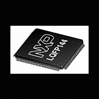
LH75401_LH75411_N NXP Semiconductors, LH75401_LH75411_N Datasheet - Page 24

LH75401_LH75411_N
Manufacturer Part Number
LH75401_LH75411_N
Description
The NXP BlueStreak LH75401/LH75411 family consists of two low-cost 16/32-bit System-on-Chip (SoC) devices
Manufacturer
NXP Semiconductors
Datasheet
1.LH75401_LH75411_N.pdf
(63 pages)
LH75401/LH75411
FUNCTIONAL OVERVIEW
ARM7TDMI-S Processor
ARM7TDMI-S core with an Advanced High-Performance
Bus (AHB) 2.0 interface. The ARM7TDMI-S is a 16/32-bit
embedded RISC processor and a member of the ARM7
Thumb family of processors. For more information, visit
the ARM Web site at www.arm.com.
Bus Architecture
ARM Advanced Microcontroller Bus Architecture (AMBA)
2.0 internal bus protocol. Three AHB masters control
access to external memory and on-chip peripherals:
• The ARM processor fetches instructions and trans-
• The Direct Memory Access Controller (DMAC) trans-
• The LCDC refreshes an LCD panel with data from
ter. An Advanced Peripheral Bus (APB) bridge is pro-
vided to access to the various APB peripherals.
Generally, APB peripherals are serviced by the ARM
core. However, if they are DMA-enabled, they are also
serviced by the DMAC to increase system performance
while the ARM core runs from local internal memory.
24
fers data
fers from memory to memory, from peripheral to
memory, and from memory to peripheral
the external memory or from internal memory if the
frame buffer is 16 kB or less.
The LH75401/LH75411 microcontrollers feature the
The LH75401/LH75411 microcontrollers use the
The ARM7TDMI-S processor is the default bus mas-
Figure 4. LH75401 System Application Example
NETWORK
SENSOR
ARRAY
CAN
A/D
TRANSCEIVER
CAN
CAN
2.0B
UART
NXP Semiconductors
Rev. 01 — 16 July 2007
LH75401
LCD
STN/TFT,
AD-TFT/HR-TFT
MATRIX
1
4
7
*
KEY
2
5
8
0
GPIO
3
6
9
#
Power Supplies
LH75401/LH75411 microcontrollers require a single
3.3 V supply. The core logic requires 1.8 V, supplied by
an on-chip linear regulator. Core logic power may also
be supplied externally to achieve higher system
speeds. See the Electrical Specifications.
Clock Sources
two crystal oscillators, or an externally supplied clock.
There are two clock trees:
• One clock tree drives an internal Phase Lock Loop
• The other is a 32.768 kHz oscillator that generates a
clocks, so an oscillator frequency of 14.7456 MHz is rec-
ommended to achieve modem baud rates.
supplied at XTALIN; the SoC will operate to DC with the
PLL disabled. When doing so, allow XTALOUT to float.
The input clock with the PLL bypassed will be twice the
desired system operating frequency, and care must be
taken not to exceed the maximum input clock voltage.
Maximum values for system speeds and input voltages
are given in the Electrical Specifications.
(PLL) and the three UARTs. It supports a crystal
oscillator frequency range from 14 MHz to 20 MHz.
1 Hz clock for the RTC. (Use of the 32.768 kHz crys-
tal for the Real Time Clock is optional. If not using the
crystal, tie XTAL32IN to VSS and allow XTAL32OUT
to float.)
Five-Volt-tolerant 3.3 V I/Os are employed. The
The LH75401/LH75411 microcontrollers may use
The 14-to-20 MHz crystal oscillator drives the UART
The PLL may be bypassed and an external clock
TOUCH SCREEN
A/D
SSP
SERIAL
EEPROM
BOOT
ROM
SRAM
FLASH
Preliminary data sheet
LH754xx-2A
System-on-Chip


