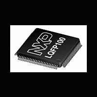
LPC12D27FBD100 NXP Semiconductors, LPC12D27FBD100 Datasheet - Page 12

LPC12D27FBD100
Manufacturer Part Number
LPC12D27FBD100
Description
The LPC12D27FBD100 is a ARM Cortex-M0 based microcontroller for embedded applications featuring a high level of integration and low power consumption
Manufacturer
NXP Semiconductors
Datasheet
1.LPC12D27FBD100.pdf
(46 pages)
Available stocks
Company
Part Number
Manufacturer
Quantity
Price
Company:
Part Number:
LPC12D27FBD100/301
Manufacturer:
NXP Semiconductors
Quantity:
10 000
NXP Semiconductors
Table 3.
LPC12D27
Product data sheet
Symbol
R/PIO1_1/AD3
PIO1_2/SWDIO/AD4
PIO1_3/AD5/WAKEUP
PIO1_4/AD6
PIO1_5/AD7/
CT16B1_CAP0/
CT16B1_MAT0
PIO1_6/CT16B1_CAP1/
CT16B1_MAT1
PIO2_0
PIO2_0/CT16B0_CAP0/
CT16B0_MAT0
RTCXIN
RTCXOUT
XTALIN
XTALOUT
VREF_CMP
V
V
V
V
LCD display pins
S0
S1
DD(IO)
DD(3V3)
SSIO
SS
LPC12D27 LQFP100 pin description
Pin
80
81
82
83
84
85
16
89
88
92
93
94
90
87
91
86
46
47
[5]
[5]
[6]
[5]
[5]
[2]
[2]
Start
logic
input
no
no
no
no
no
no
no
-
-
-
-
-
-
-
-
-
-
-
Reset
state
[1]
-
-
-
-
-
-
V
V
I; PU
I; PU
I; PU
I; PU
I; PU
I; PU
I; PU
-
-
-
All information provided in this document is subject to legal disclaimers.
LCD
LCD
[8]
[8]
Rev. 1 — 20 September 2011
Type
I
I/O
I
I/O
I/O
I
I/O
I
I
I/O
I
I/O
I
I
O
I/O
I
O
I/O
I/O
I
O
-
-
-
-
-
-
-
-
-
O
O
…continued
Description
R — Reserved. Configure for an alternate function in the
IOCONFIG block.
PIO1_1 — General purpose digital input/output pin.
AD3 — A/D converter, input 3.
PIO1_2 — General purpose digital input/output pin.
SWDIO — Serial wire debug input/output, alternate location.
AD4 — A/D converter, input 4.
PIO1_3 — General purpose digital input/output pin.
AD5 — A/D converter, input 5.
WAKEUP — Deep power-down mode wake-up pin.
PIO1_4 — General purpose digital input/output pin.
AD6 — A/D converter, input 6.
PIO1_5 — General purpose digital input/output pin.
AD7 — A/D converter, input 7.
CT16B1_CAP0 — Capture input, channel 0 for 16-bit timer 1.
CT16B1_MAT0 — Match output, channel 0 for 16-bit timer 1.
PIO1_6 — General purpose digital input/output pin.
CT16B1_CAP1 — Capture input, channel 1 for 16-bit timer 1.
CT16B1_MAT1 — Match output, channel 1 for 16-bit timer 1.
Port 2 — Port 2 is a 32-bit I/O port with individual direction and
function controls for each bit. The operation of port 2 pins
depends on the function selected through the IOCONFIG register
block. Pins PIO2_1 through PIO2_31 are not available.
PIO2_0 — General purpose digital input/output pin.
CT16B0_CAP0 — Capture input, channel 0 for 16-bit timer 0.
CT16B0_MAT0 — Match output, channel 0 for 16-bit timer 0.
Input to the 32 kHz oscillator circuit.
Output from the 32 kHz oscillator amplifier.
Input to the system oscillator circuit and internal clock generator
circuits.
Output from the system oscillator amplifier.
Reference voltage for comparator.
Input/output supply voltage.
3.3 V supply voltage to the internal regulator and the ADC. Also
used as the
ADC reference voltage.
Ground.
Ground.
LCD segment output.
LCD segment output.
32-bit ARM Cortex-M0 microcontroller
LPC12D27
© NXP B.V. 2011. All rights reserved.
12 of 46


