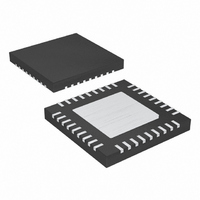
MAX9742ETX+ Maxim Integrated Products, MAX9742ETX+ Datasheet - Page 21

MAX9742ETX+
Manufacturer Part Number
MAX9742ETX+
Description
IC AMP AUDIO PWR 20.5W D 36TQFN
Manufacturer
Maxim Integrated Products
Type
Class Dr
Datasheet
1.MAX9742ETX.pdf
(36 pages)
Specifications of MAX9742ETX+
Output Type
2-Channel (Stereo)
Max Output Power X Channels @ Load
20.5W x 2 @ 8 Ohm
Voltage - Supply
20 V ~ 40 V, ±10 V ~ 20 V
Features
Depop, Differential Inputs, Mute, Short-Circuit and Thermal Protection, Shutdown
Mounting Type
Surface Mount
Package / Case
36-TQFN Exposed Pad
Product
Class-D
Output Power
16 W
Thd Plus Noise
0.08 %
Supply Current
15 mA
Maximum Power Dissipation
2.86 W
Maximum Operating Temperature
+ 85 C
Mounting Style
SMD/SMT
Audio Load Resistance
4 Ohms
Minimum Operating Temperature
- 40 C
Lead Free Status / RoHS Status
Lead free / RoHS Compliant
Table 1. Recommended LC Filter
Component Values for Various Speaker
Loads (f
Table 2. Suggested Inductor Manufacturers
Using the transfer functions and the equation for f
following expressions for L
Since the frequency response of the output filter is
dependent on the speaker resistance, it is best to opti-
mize the LC filter for a particular load resistance. To
calculate the component values of the LC filter for a
given speaker load resistance, first select an appropri-
ate cutoff frequency for the filter. The cutoff frequency
should be high enough so that upper audio frequency
band attenuation is kept to a minimum while providing
sufficient attenuation at the switching frequency (f
the MAX9742. Once the cutoff frequency is determined,
calculate C
(R
calculate L
When selecting C
ings greater than V
When selecting L
the DC resistance, current capabilities, and upper fre-
quency limitations of the inductor. Choosing an induc-
tor with minimum DC resistance minimizes I
due to the filter inductor and therefore preserves power
efficiency. The inductor current rating should be
greater than the maximum peak output current to pre-
vent the inductor from going into saturation. Output
inductor saturation introduces nonlinearities into the
output signal and therefore increases distortion. The
DO3340P
CDRH127
11RHBP
SLF12575
DC RESISTANCE OF SPEAKER (Ω)
SPKR
) and a damping ratio (ζ) equal to 0.707. Finally,
C
C
F
MODEL
F
F
using the resulting C
L
= 40kHz)
using the DC resistance of the speaker
=
F
=
Class D Amplifier with Differential Inputs
4
4
6
8
F
F
______________________________________________________________________________________
, use capacitors with DC voltage rat-
DD
, it is important to take into account
×
4
×
π
.
×
π
2
f
F
C
×
and C
1
1
×
f
Coilcraft
Sumida
Toko
TDK
C
R
2
SPKR
F
F
×
value.
MANUFACTURER
can be derived:
C
L
Single-/Dual-Supply, Stereo 16W,
F
F
×
22
33
47
(µH)
( )
H
ζ
( )
F
2
R losses
C
F
0.68
0.47
0.33
SW
c
(µF)
, the
) of
12.95mm x 9.4mm x 11.43mm
12.3mm x 12.3mm x 8mm
11mm x 11mm x 13.75mm
12.5mm x 12.5mm x 7.5mm
upper frequency limit of the inductor should also be
taken into account. The load connected to the output of
the half-bridge (LC filter and speaker) should remain
inductive at the switching frequency of the MAX9742. If
not, a significant amount of high-frequency energy is
dissipated in the resistive load, therefore, increasing
the supply current to excessive levels. To prevent this
from occurring, select an output inductor whose self-
resonant frequency is substantially higher than the
switching frequency of the MAX9742.
To minimize possible EMI radiation, place the LC filter
near the MAX9742 on the PCB.
Table 2 provides some suggested inductor manufac-
turers.
When using the BTL configuration, optimize the output fil-
ter for fully differential operation (see Figure 9 and Table
3). Follow the design criteria provided for the single-
ended filter except use half the value of the BTL resis-
tance for the output filter calculations. This is because
each half-bridge output sees half of the BTL resistance.
For example, with a BTL resistance of 8Ω the ideal filter
component values are C
maximally flat differential filter response with an approxi-
mate cutoff frequency of 40kHz. Rounding to the nearest
standard component values yields C
22µH. Also connect ground-terminated Zobel networks
on each side of the speaker load (see the Zobel Network
section). Ground terminating the Zobel networks pre-
vents excessive peaking in the common-mode frequen-
cy response of the filter.
Figure 8. Single-Ended LC Output Filter
NOTE: AN OUTPUT-COUPLING CAPACITOR (C
SINGLE-ENDED OUTPUT CONFIGURATION.
OUT_
DIMENSIONS
SINGLE-ENDED OUTPUT FILTER
L
F
F
C
BTL LC Output Filter Design
F
= 0.7µF and L
www.coilcraft.com
www.sumida.com
www.tokoam.com
www.component.tdk.com
OUT
) IS NEEDED FOR SINGLE-SUPPLY,
R
F
SPKR
WEBSITE
= 0.68µF and L
F
= 22.5µH for a
F
21
=


