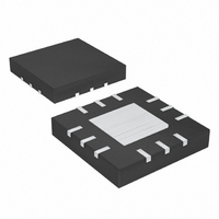
MAX9725AETC+T Maxim Integrated Products, MAX9725AETC+T Datasheet - Page 9

MAX9725AETC+T
Manufacturer Part Number
MAX9725AETC+T
Description
IC AMP AUDIO .025W STER 12TQFN
Manufacturer
Maxim Integrated Products
Series
DirectDrive™r
Type
Class ABr
Datasheet
1.MAX9725CETCT.pdf
(17 pages)
Specifications of MAX9725AETC+T
Output Type
Headphones, 2-Channel (Stereo)
Max Output Power X Channels @ Load
25mW x 2 @ 16 Ohm
Voltage - Supply
900 mV ~ 1.8 V
Features
Depop, Short-Circuit Protection, Shutdown
Mounting Type
Surface Mount
Package / Case
12-TQFN Exposed Pad
Lead Free Status / RoHS Status
Lead free / RoHS Compliant
Large DC-blocking capacitors limit the amplifier’s low-
frequency response and can distort the audio signal:
1) The impedance of the headphone load and the DC-
2) The voltage coefficient of the DC-blocking capacitor
Figure 2. Low-Frequency Attenuation for Common DC-Blocking
Capacitor Values
1V, Low-Power, DirectDrive, Stereo Headphone
blocking capacitor forms a highpass filter with the
-3dB point set by:
where R
C
highpass filter is required by conventional single-
ended, single power-supply headphone drivers to
block the midrail DC-bias component of the audio
signal from the headphones. The drawback to the
filter is that it can attenuate low-frequency signals.
Larger values of C
in physically larger, more expensive capacitors.
Figure 2 shows the relationship between the size of
C
Note that the -3dB point for a 16Ω headphone with
a 100µF blocking capacitor is 100Hz, well within the
normal audio band, resulting in low-frequency
attenuation of the reproduced signal.
contributes distortion to the reproduced audio signal
as the capacitance value varies when the function of
the voltage across the capacitor changes. At low
frequencies, the reactance of the capacitor domi-
nates at frequencies below the -3dB point and the
OUT
OUT
-10
-15
-20
-25
-30
-35
is the value of the DC-blocking capacitor. The
and the resulting low-frequency attenuation.
-3
-5
0
L
10
is the impedance of the headphone and
330μF
f
-3dB
_______________________________________________________________________________________
LF ROLLOFF (16Ω LOAD)
220μF
100μF
=
OUT
33μF
FREQUENCY (Hz)
2 R C
π
100
reduce this effect but result
L OUT
Low-Frequency Response
1
-3dB CORNER FOR
100μF IS 100Hz
1k
Amplifier with Shutdown
The combination of low-frequency attenuation and fre-
quency-dependent distortion compromises audio
reproduction in portable audio equipment that empha-
sizes low-frequency effects such as multimedia lap-
tops, as well as MP3, CD, and DVD players. These
low-frequency, capacitor-related deficiencies are elimi-
nated by using DirectDrive technology.
The MAX9725 features a low-noise charge pump. The
580kHz switching frequency is well beyond the audio
range, and does not interfere with the audio signals.
The switch drivers feature a controlled switching speed
that minimizes noise generated by turn-on and turn-off
transients. The di/dt noise caused by the parasitic bond
wire and trace inductance is minimized by limiting the
turn-on/off speed of the charge pump. Additional high-
frequency noise attenuation can be achieved by
increasing the size of C2 (see the Functional Diagrams ).
Extra noise attenuation is not typically required.
The MAX9725’s low-power shutdown mode reduces
supply current to 0.6µA. Driving SHDN low disables the
amplifiers and charge pump. The driver’s output imped-
ance is typically 50kΩ (MAX9725A), 37.5kΩ
(MAX9725B), 25kΩ (MAX9725C), 100kΩ (MAX9725D),
or R
Figure 3. Distortion Contributed By DC-Blocking Capacitors
voltage coefficient appears as frequency-dependent
distortion. Figure 3 shows the THD+N introduced by
two different capacitor dielectric types. Note that
below 100Hz, THD+N increases rapidly.
F
(MAX9725E) when in shutdown mode.
0.0001
0.001
0.01
0.1
10
1
10
TO DC-BLOCKING CAPACITORS
ALUM/ELEC
ADDITIONAL THD+N DUE
100
FREQUENCY (Hz)
TANTALUM
1k
10k
Charge Pump
Shutdown
100k
9


