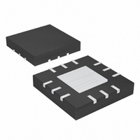
MAX9725AETC+T Maxim Integrated Products, MAX9725AETC+T Datasheet - Page 7

MAX9725AETC+T
Manufacturer Part Number
MAX9725AETC+T
Description
IC AMP AUDIO .025W STER 12TQFN
Manufacturer
Maxim Integrated Products
Series
DirectDrive™r
Type
Class ABr
Datasheet
1.MAX9725CETCT.pdf
(17 pages)
Specifications of MAX9725AETC+T
Output Type
Headphones, 2-Channel (Stereo)
Max Output Power X Channels @ Load
25mW x 2 @ 16 Ohm
Voltage - Supply
900 mV ~ 1.8 V
Features
Depop, Short-Circuit Protection, Shutdown
Mounting Type
Surface Mount
Package / Case
12-TQFN Exposed Pad
Lead Free Status / RoHS Status
Lead free / RoHS Compliant
(V
to 22kHz, T
DD
THIN
QFN
1V, Low-Power, DirectDrive, Stereo Headphone
PIN
0.7
0.6
0.5
0.4
0.3
0.2
0.1
EP
10
11
12
0
1
2
3
4
5
6
7
8
9
= 1.5V, V
0.9
A
BUMP
UCSP
= +25°C, unless otherwise noted.) (See the Functional Diagrams. )
C4
C3
C2
C1
A1
A2
A3
A4
B4
B3
B1
B2
SHUTDOWN CURRENT
vs. SUPPLY VOLTAGE
—
PGND
SUPPLY VOLTAGE (V)
1.1
= V
_______________________________________________________________________________________
NAME
SGND
OUTR
PGND
SHDN
OUTL
PV
C1N
C1P
V
SGND
INR
V
INL
EP
DD
SS
SS
1.3
= 0V, V
Flying Capacitor Negative Terminal. Connect a 1µF capacitor from C1P to C1N.
Inverting Charge-Pump Output. Bypass with 1µF from PV
V
Left-Amplifier Inverting Input. Connect input resistor R
only).
Right-Amplifier Inverting Input. Connect input resistor R
(MAX9725E only).
Amplifier Negative Power Supply. Must be connected to PV
Signal Ground. SGND must be connected to PGND. SGND is the ground reference for the input and
output signal.
Right-Channel Output. Connect feedback resistor R
Left-Channel Output. Connect feedback resistor R
Positive Power-Supply Input. Bypass with a 1µF capacitor to PGND.
Flying Capacitor Positive Terminal. Connect a 1µF capacitor from C1P to C1N.
Power Ground. Ground reference for the internal charge pump. PGND must be connected to SGND.
Active-Low Shutdown. Connect to V
charge pump.
Exposed Paddle. Internally connected to V
SS
.
SHDN
1.5
500mV/div
= 1.5V, V
1V/div
SHDN
OUT_
Typical Operating Characteristics (continued)
SS
= V
EXITING SHUTDOWN
PVSS,
200μs/div
Amplifier with Shutdown
C1 = C2 = 1µF, C
DD
for normal operation. Pull low to disable the amplifier and
SS
FUNCTION
. Leave paddle unconnected or solder to V
MAX9725 toc23
FB
IN
FB
between OUTL and INL (MAX9725E only).
= 1µF, THD+N measurement bandwidth = 22Hz
IN
between OUTR and INR (MAX9725E only).
IN
from input capacitor C1N to INL (MAX9725E
SS
from input capacitor C1N to INR
SS
to PGND. PV
.
POWER-UP/-DOWN WAVEFORM
SS
200ms/div
Pin Description
must be connected to
MAX9725toc24
SS
.
V
1V/div
OUT_
10mV/div
DD
7


