TDA7293V STMicroelectronics, TDA7293V Datasheet - Page 12
TDA7293V
Manufacturer Part Number
TDA7293V
Description
IC AMP AUDIO 100W AB MULTIWATT15
Manufacturer
STMicroelectronics
Type
Class ABr
Datasheet
1.TDA7293V.pdf
(21 pages)
Specifications of TDA7293V
Output Type
1-Channel (Mono)
Max Output Power X Channels @ Load
100W x 1 @ 4 Ohm
Voltage - Supply
±12 V ~ 50 V
Features
Depop, Differential Inputs, Mute, Short-Circuit and Thermal Protection, Standby
Mounting Type
Through Hole
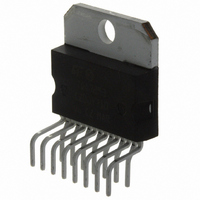
Package / Case
Multiwatt-15 (Vertical, Bent and Staggered Leads)
Product
Class-AB
Output Power
100 W
Available Set Gain
80 dB
Thd Plus Noise
0.005 %
Operating Supply Voltage
+/- 60 V
Supply Current
10 A
Maximum Power Dissipation
50000 mW
Maximum Operating Temperature
+ 70 C
Mounting Style
Through Hole
Audio Load Resistance
8 Ohms
Dual Supply Voltage
+/- 15 V, +/- 18 V, +/- 24 V, +/- 28 V
Input Bias Current (max)
1 uA
Input Offset Voltage
10 mV
Input Signal Type
Single
Minimum Operating Temperature
0 C
Output Signal Type
Single
Supply Type
Dual
Amplifier Class
AB
No. Of Channels
1
Supply Voltage Range
± 12V To ± 50V
Load Impedance
4ohm
Operating Temperature Range
0°C To +70°C
Amplifier Case Style
Multiwatt15
Rohs Compliant
Yes
Lead Free Status / RoHS Status
Lead free / RoHS Compliant
Other names
497-2170-5
Available stocks
Company
Part Number
Manufacturer
Quantity
Price

Part Number:
TDA7293V
Manufacturer:
ST
Quantity:
20 000


Applications information
4.4
4.5
12/21
Modular application (ref. figure 12)
The modular application is where several devices operate in parallel.
The modular application allows very high power be delivered to very low-impedance loads.
In this type of application one device acts as a master and the others as slaves.
The slave power stages are driven by the master device and work in parallel together while
the input and the gain stages of the slave devices are disabled. The figure below shows the
connections required to configure two devices to work together.
Bootstrap capacitor
For compatibility purpose with the previous devices of the family, the bootstrap capacitor can
be connected either between the bootstrap pin (6) and the output pin (14) or between the
bootstrap pin (6) and the bootstrap loader pin (12).
When the bootstrap is connected between pins 6 and 14 the maximum supply voltage in the
presence of an output signal is limited to 100 V, due the bootstrap capacitor overvoltage.
When the bootstrap is connected between pins 6 and 12 the maximum supply voltage
extends to the full voltage that the technology can stand, in this case 120 V.
This is accomplished by the clamp introduced at the bootstrap loader pin (12). This pin
follows the output voltage up to 100 V and remains clamped at 100 V for higher output
voltages.
This feature lets the output voltage swing up to a gate-source voltage from the positive
supply (V
The master chip connections are the same as the normal single ones.
The outputs can be connected together without the need of any ballast resistor.
The slave SGND pin must be tied to the negative supply.
The slave STANDBY and MUTE pins must be connected to the master STANDBY and
MUTE pins.
The bootstrap lines must be connected together and the bootstrap capacitor must be
increased: for N devices the bootstrap capacitor must be 22 µF times N.
The slave IN pin must be connected to the negative supply.
S
-3 to 6 V).
Doc ID 6744 Rev 8
TDA7293
Related parts for TDA7293V
Image
Part Number
Description
Manufacturer
Datasheet
Request
R

Part Number:
Description:
STMicroelectronics [RIPPLE-CARRY BINARY COUNTER/DIVIDERS]
Manufacturer:
STMicroelectronics
Datasheet:
Part Number:
Description:
STMicroelectronics [LIQUID-CRYSTAL DISPLAY DRIVERS]
Manufacturer:
STMicroelectronics
Datasheet:

Part Number:
Description:
BOARD EVAL FOR MEMS SENSORS
Manufacturer:
STMicroelectronics
Datasheet:
Part Number:
Description:
NPN TRANSISTOR POWER MODULE
Manufacturer:
STMicroelectronics
Datasheet:
Part Number:
Description:
TURBOSWITCH ULTRA-FAST HIGH VOLTAGE DIODE
Manufacturer:
STMicroelectronics
Datasheet:
Part Number:
Description:
Manufacturer:
STMicroelectronics
Datasheet:
Part Number:
Description:
DIODE / SCR MODULE
Manufacturer:
STMicroelectronics
Datasheet:
Part Number:
Description:
DIODE / SCR MODULE
Manufacturer:
STMicroelectronics
Datasheet:
Part Number:
Description:
Search -----> STE16N100
Manufacturer:
STMicroelectronics
Datasheet:
Part Number:
Description:
Search ---> STE53NA50
Manufacturer:
STMicroelectronics
Datasheet:
Part Number:
Description:
NPN Transistor Power Module
Manufacturer:
STMicroelectronics
Datasheet:
Part Number:
Description:
DIODE / SCR MODULE
Manufacturer:
STMicroelectronics
Datasheet: