TDA7293V STMicroelectronics, TDA7293V Datasheet
TDA7293V
Specifications of TDA7293V
Available stocks


Related parts for TDA7293V


TDA7293V Summary of contents
Page 1
... The built-in muting function with turn-on delay simplifies the remote operation avoiding on-off switching noises. Parallel mode is possible by connecting several devices and using pin11. High output power can be delivered to very low impedance loads, so optimizing the thermal dissipation of the system Table 1. TDA7293V TDA7293HS C7 100nF R3 22K BUFFER DRIVER + 680Ω ...
Page 2
Contents Contents 1 Pin connections . . . . . . . . . . . . . . . . . . . . . . . . . . . . . . . . . . . ...
Page 3
TDA7293 1 Pin connections Figure 2. Pin connections TAB CONNECTED TO PIN (POWER OUT 13 +V (POWER BOOTSTRAP LOADER 11 BUFFER DRIVER 10 MUTE 9 STAND- (SIGNAL (SIGNAL) ...
Page 4
Electrical specifications 2 Electrical specifications 2.1 Absolute maximum ratings Table 2. Absolute maximum ratings Symbol V Supply voltage (no signal STANDBY V Input voltage (inverting) referred Maximum differential inputs 2 ...
Page 5
TDA7293 2.3 Electrical characteristics The specifications given here were obtained with the conditions Ω ° kHz unless otherwise specified. g amb . Table 4. Electrical characteristics Symbol Parameter V Supply ...
Page 6
Electrical specifications Table 4. Electrical characteristics (continued) Symbol Parameter Clip detector Duty Duty cycle ( pin CLEAK Slave function pin 4 (ref. to pin 8) V Slavethreshold Slave V Master threshold Master 1. Tested with optimized applications ...
Page 7
TDA7293 3 Circuit description In consumer electronics, an increasing demand has arisen for very high power monolithic audio amplifiers able to match, with a low cost, the performance obtained from the best discrete designs. The task of realizing this linear ...
Page 8
Circuit description While a linearization of the DC transfer characteristic of the stage is obtained, the dynamic behaviour of the system must be taken into account. A significant aid in keeping the distortion contributed by the final stage as low ...
Page 9
TDA7293 Figure 5. Suggested turn-on/off sequence Figure 6. Single signal standby/mute control circuit +Vs (V) +40 -40 - (mV) V ST-BY 5V PIN #9 (V) V MUTE 5V PIN #10 ( (mA) V OUT (V) OFF ...
Page 10
Applications information 4 Applications information 4.1 Applications suggestions The recommended values of the external components are those shown on the application circuit of Figure 1 on page could be useful when choosing alternative values. Table 5. Choosing alternative component values ...
Page 11
TDA7293 4.2 High efficiency Constraints of implementing high power solutions are the power dissipation and the size of the power supply. These are both due to the low efficiency of conventional AB class amplifier approaches. The circuit below in and ...
Page 12
Applications information 4.4 Modular application (ref. figure 12) The modular application is where several devices operate in parallel. The modular application allows very high power be delivered to very low-impedance loads. In this type of application one device acts as ...
Page 13
TDA7293 Figure 8. High-efficiency applications circuit +50V +25V R20 C1 C3 20K 1000µF 100nF 1000µF 63V GND R21 C2 C4 20K 1000µF 100nF 1000µF 63V -25V -50V Figure 9. PCB and component layout of fig 1N4001 D1 BYW98100 ...
Page 14
Applications information Figure 10. PCB - solder side of the Fig 9 Figure 11. Modular application circuit MASTER C2 22µF VMUTE R5 10K VSTBY R4 22K SLAVE 14/21 C7 100nF R3 22K BUFFER +Vs DRIVER R2 7 680Ω IN- 2 ...
Page 15
TDA7293 Figure 12. Modular application PCB and component layout (component side) Figure 13. Modular application PCB and component layout (solder side) Doc ID 6744 Rev 8 Applications information 15/21 ...
Page 16
Applications information Figure 14. Distortion vs output power Figure 16. Distortion vs frequency Figure 18. Modular application Pd vs voltage supply (ref. fig. 12) 16/21 Figure 15. Distortion vs output power Figure 17. Modular application derating rload vs voltage supply ...
Page 17
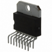
TDA7293 5 Package mechanical data The TDA7293 comes with a choice of two 15-pin packages, Multiwatt15V and Multiwatt15H. The package sizes and outline drawings are given below. 5.1 Vertically-mounted package Figure 20. Multiwatt15V package DIM. MIN ...
Page 18
Package mechanical data 5.2 Horizontally-mounted package Figure 21. Multiwatt15H outline 18/21 Doc ID 6744 Rev 8 TDA7293 ...
Page 19
TDA7293 Table 6. Multiwatt15H dimensions Ref 0.49 F 0.66 G 1.02 G1 17.53 H1 19.60 H2 19.60 L1 17.80 L2 2.30 L3 17.25 L4 10.30 L5 2. ...
Page 20
Revision history 6 Revision history Table 7. Document revision history Date Jan-2004 Aug-2004 24-Sep-2010 20/21 Revision 7 First Issue in EDOCS 7.1 Stylesheet update. No content change Updated package dimensions for Multiwatt15H in 8 Updated presentation throughout document. Doc ID ...
Page 21
... TDA7293 Information in this document is provided solely in connection with ST products. STMicroelectronics NV and its subsidiaries (“ST”) reserve the right to make changes, corrections, modifications or improvements, to this document, and the products and services described herein at any time, without notice. All ST products are sold pursuant to ST’s terms and conditions of sale. ...