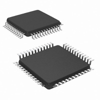
NS16C2552TVS/NOPB National Semiconductor, NS16C2552TVS/NOPB Datasheet - Page 6

NS16C2552TVS/NOPB
Manufacturer Part Number
NS16C2552TVS/NOPB
Description
IC UART DUAL 16BYTE 48-TQFP
Manufacturer
National Semiconductor
Datasheet
1.NS16C2552TVAXNOPB.pdf
(44 pages)
Specifications of NS16C2552TVS/NOPB
Features
Programmable
Number Of Channels
2, DUART
Fifo's
16 Byte
Voltage - Supply
2.97 V ~ 5.5 V
With Auto Flow Control
Yes
With Irda Encoder/decoder
Yes
With Modem Control
Yes
Mounting Type
Surface Mount
Package / Case
48-VFQFP
Lead Free Status / RoHS Status
Lead free / RoHS Compliant
Other names
NS16C2552TVS
Available stocks
Company
Part Number
Manufacturer
Quantity
Price
Company:
Part Number:
NS16C2552TVS/NOPB
Manufacturer:
Texas Instruments
Quantity:
10 000
www.national.com
TXRDY1
TXRDY2
INTR1
INTR2
SOUT1
SOUT2
SIN1
SIN2
RTS1
RTS2
DTR1
DTR2
CTS1
CTS2
DSR1
DSR2
Signal
Signal
Name
Name
5.2 SERIAL IO INTERFACE
Type
Type
O
O
O
I
I
I
O
O
PLCC
Pin #
38
26
39
25
36
23
37
27
40
28
41
29
PLCC
Pin #
32
34
17
1
TQFP
Pin #
35
22
36
21
33
18
34
23
38
24
39
25
TQFP
Pin #
43
28
30
12
UART Serial Data Out:
UART transmit data output or infrared data output. The SOUT signal is set to logic 1 upon reset
or idle in the UART mode when MCR[6]=0. The SOUT signal transitions to logic 0 (idle state of
IrDA mode) in the infrared mode when MCR[6]=1.
Note: SOUT1 and SOUT2 can not be reset to IrDA mode.
UART Serial Data In:
UART receive data input or infrared data input. The SIN should be idling in logic 1 in the UART
mode. The SIN should be idling in logic 0 in the infrared mode. The SIN should be pulled high
through a 10K resistor if not used.
UART Request-to-send:
When low, RTS informs the remote link partner that it is ready to receive data. The RTS output
signal can be set to an active low by writing “1” to MCR[1]. The RTS output can also be
configured in auto hardware flow control based on FIFO trigger level. This pin stays logic 1 upon
reset or idle (i.e., between data transfers). Loop mode operation holds this signal in its inactive
state.
UART Data-terminal-ready:
When low, DTR informs the remote link partner that the UART is ready to establish a
communications link. The DTR output signal can be set to an active low by writing “1” to MCR
[0]. This pin stays at logic 1 upon reset or idle. Loop mode operation holds this signal to its
inactive state.
UART Clear-to-send:
When low, CTS indicates that the remote link partner is ready to receive data. The CTS signal
is a modem status input and can be read for the appropriate channel in MSR[4]. This bit reflects
the complement of the CTS signal. MSR[0] indicates whether the CTS input has changed state
since the previous read of the MSR. CTS can also be configured to perform auto hardware flow
control.
Note: Whenever the CTS bit of the MSR changes state, an interrupt is generated if the MODEM Status Interrupt is
UART Data-set-ready:
When low, DSR indicates that the remote link partner is ready to establish the communications
link. The DSR signal is a MODEM status input and can be read for the appropriate channel in
MSR[5]. This bit reflects the complement of the DSR signal. MSR[1] indicates whether the
DSR input has changed state since the previous read of the MODEM Status Register.
Note: Whenever the DSR bit of the MSR changes state, an interrupt is generated if the MODEM Status Interrupt is
UART Transmit-ready:
Transmitter DMA signaling is available through this pin. When operating in the FIFO mode,
the CPU selects one of two types of DMA transfer via FCR[3]. When operating in the 16450
Mode, only DMA mode 0 is allowed. Mode 0 supports single transfer DMA (and a transfer
is usually made between CPU bus cycles). Mode 1 supports multi-transfer DMA where
multiple transfers are made continuously until the Tx FIFO is full. Details regarding the
active and inactive states of this signal are described in Section 6.5 FIFO CONTROL
REGISTER (FCR) and Section 7.9 DMA OPERATION.
Interrupt Output:
INTR goes high whenever any one of the following interrupt types has an active high
condition and is enabled via the IER: Receiver Error Flag; Received Data Available: time-
out (FIFO Mode only); Transmitter Holding Register Empty; MODEM Status; and hardware
and software flow control. The INTR signal is reset low upon the appropriate interrupt
service or a Master Reset operation.
enabled.
enabled.
6
Description
Description


