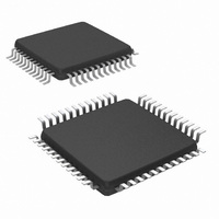
NS16C2552TVS/NOPB National Semiconductor, NS16C2552TVS/NOPB Datasheet - Page 23

NS16C2552TVS/NOPB
Manufacturer Part Number
NS16C2552TVS/NOPB
Description
IC UART DUAL 16BYTE 48-TQFP
Manufacturer
National Semiconductor
Datasheet
1.NS16C2552TVAXNOPB.pdf
(44 pages)
Specifications of NS16C2552TVS/NOPB
Features
Programmable
Number Of Channels
2, DUART
Fifo's
16 Byte
Voltage - Supply
2.97 V ~ 5.5 V
With Auto Flow Control
Yes
With Irda Encoder/decoder
Yes
With Modem Control
Yes
Mounting Type
Surface Mount
Package / Case
48-VFQFP
Lead Free Status / RoHS Status
Lead free / RoHS Compliant
Other names
NS16C2552TVS
Available stocks
Company
Part Number
Manufacturer
Quantity
Price
Company:
Part Number:
NS16C2552TVS/NOPB
Manufacturer:
Texas Instruments
Quantity:
10 000
Bit
7:0
Bit
7:0
6.10 SCRATCHPAD REGISTER (SCR)
This 8-bit Read/Write Register does not control the serial
channel in any way. It is intended as a Scratchpad Register
to be used by the programmer to hold data temporarily.
6.11 PROGRAMMABLE BAUD GENERATOR
The NS16C2552 contains two independently programmable
Baud Generators. Each is capable of taking prescaler input
and dividing it by any divisor from 1 to 2
highest input clock frequency recommended with a divisor =
1 is 80MHz. The output frequency of the Baud Generator is
16 X the baud rate, [divisor # = (frequency input) / (baud rate
Table 17 provides decimal divisors to use with crystal fre-
quencies of 1.8432 MHz, 3.072 MHz and 18.432 MHz. For
baud rates of 38400 and below, the error obtained is minimal.
Note: For baud rates of 250k, 300k, 375k, 500k, 750k and 1.5M using a
Bit
7:0
Output Data
Baud Rate
115,200
19,200
38,400
24MHz crystal causes minimal error.
DLM Data
1200
2400
4800
9600
Bit Name
Bit Name
DLL Data
150
300
600
50
75
SCR Data
Bit Name
0xXX
0xXX
R/W
R/W
R/W
R/W
Def
Output 16x Clock
Def
Divider (dec)
TABLE 17. Baud Rate Generation Using 1.8432 MHz Clock with MCR[7]=0
0xFF
R/W
R/W
2304
1536
Def
768
384
192
96
48
24
12
Divisor Latch MSB
This 8-bit register holds the most significant byte of the 16-bit baud rate generator divisor.
Note: This register value does not change upon MR reset.
Divisor Latch LSB
This 8-bit register holds the least significant byte of the 16-bit baud rate generator divisor.
Note: This register value does not change upon MR reset.
6
3
1
TABLE 16. DLM (0x1, LCR[7] = 1, LCR != 0xBF)
Scratchpad Register
This 8-bit register does not control the UART in any way. It is intended as a scratchpad register
to be used by the programmer to hold temporary data.
TABLE 15. DLL (0x0, LCR[7] = 1, LCR != 0xBF)
16
-1 (Figure 1). The
User 16x Clock
Divisor (hex)
TABLE 14. SCR (0x7)
900
600
300
180
C0
0C
60
30
18
06
03
01
23
X 16)]. The output of each Baud Generator drives the trans-
mitter and receiver sections of the associated serial channel.
Two 8-bit latches per channel store the divisor in a 16-bit bi-
nary format. These Divisor Latches must be loaded during
initialization to ensure proper operation of the Baud Genera-
tor. Upon loading either of the Divisor Latches, a 16-bit Baud
Counter is loaded.
The accuracy of the desired baud rate is dependent on the
crystal frequency chosen. Using a divisor of zero is not rec-
ommended.
DLM Program
Value (hex)
Description
Description
09
06
03
01
00
00
00
00
00
00
00
00
Description
DLL Program
Value (hex)
C0
0C
00
00
00
80
60
30
18
06
03
01
Data Rate
www.national.com
Error (%)
0
0
0
0
0
0
0
0
0
0
0
0


