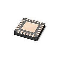
MAX3107ETG+ Maxim Integrated Products, MAX3107ETG+ Datasheet - Page 33

MAX3107ETG+
Manufacturer Part Number
MAX3107ETG+
Description
IC UART SPI/I2C 128 FIFO 24TQFN
Manufacturer
Maxim Integrated Products
Datasheet
1.MAX3107EAG.pdf
(52 pages)
Specifications of MAX3107ETG+
Features
Internal Oscillators
Number Of Channels
4, QUART
Fifo's
128 Byte
Protocol
RS232, RS485
Voltage - Supply
2.35 V ~ 3.6 V
With Auto Flow Control
Yes
With Irda Encoder/decoder
Yes
With False Start Bit Detection
Yes
Mounting Type
Surface Mount
Package / Case
24-TQFN Exposed Pad
Data Rate
24 Mbps
Supply Voltage (max)
3.3 V
Supply Voltage (min)
2.35 V
Supply Current
0.64 mA
Maximum Operating Temperature
+ 85 C
Minimum Operating Temperature
- 40 C
Mounting Style
SMD/SMT
No. Of Channels
1
Uart Features
128-Word Transmit / Receive FIFO, Half-Duplex Echo Suppression, Shutdown And Autosleep Modes
Supply Voltage Range
2.35V To 3.6V
Rohs Compliant
Yes
Lead Free Status / RoHS Status
Lead free / RoHS Compliant
LCR—Line Control Register
Bit 7: RTS
The RTS bit gives direct control of the RTS/CLKOUT output logic. If the RTS bit is set high, then RTS/CLKOUT is set to
logic-high. The RTS bit only works if the CLKSource[7]:CLKtoRTS is not set high.
Bit 6: TxBreak
Set TxBreak to 1 to generate a line break whereby the TX output is held low until TxBreak is set to 0.
Bit 5: ForceParity
ForceParity enables forced parity, as used in 9-bit multidrop communication. Set both LCR[3] and ForceParity to use
forced parity. The parity bit is forced high by the transmitter if LCR[4] low. The parity bit is forced low if LCR[4] is high.
Bit 4: EvenParity
Set EvenParity high to enable even parity. If EvenParity is set low odd parity generation/checking is used.
Bit 3: ParityEn
The ParityEn bit enables the use of a parity bit on the TX and RX interfaces. When ParityEn is low, then parity usage
is disabled. When ParityEn is set to 1, the transmitter generates the parity bit as defined in LCR[4] and the receiver
checks the received parity bit.
Bit 2: StopBits
This defines the number of STOP bits and depends on the length of the word programmed in LCR[1:0] (Table 1). When
StopBits is high and the word length is 5, the transmitter generates a word with a STOP bit length equal to 1.5. Under
these conditions, the receiver recognizes a STOP bit length greater than a 1-bit duration.
Bits 1 and 0: Length[1:0]
The Length[1:0] bits configure the length of the words that the transmitter generates and the receiver checks for at the
asynchronous TX and RX interfaces (Table 2).
Table 1. StopBits Truth Table
ADDRESS:
MODE:
LCR[2]
RESET
NAME
BIT
0
1
1
WORD LENGTH
5, 6, 7, 8
______________________________________________________________________________________
RTS
6, 7, 8
7
0
5
0x0B
R/W
TxBreak
SPI/I
6
0
STOP BIT LENGTH
ForceParity
1–1.5
2
1
2
5
0
C UART with 128-Word FIFOs
EvenParity
4
0
Table 2. Length[1:0] Truth Table
and Internal Oscillator
Length1
ParityEn
0
0
1
1
3
0
StopBits
2
1
Length0
0
1
0
1
Length1
1
0
WORD LENGTH
Length0
5
6
7
8
0
1
33


