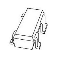
BF1101WRT NXP Semiconductors, BF1101WRT Datasheet - Page 9

BF1101WRT
Manufacturer Part Number
BF1101WRT
Description
Manufacturer
NXP Semiconductors
Datasheet
1.BF1101WRT.pdf
(15 pages)
Specifications of BF1101WRT
Application
VHF/UHF
Channel Type
N
Channel Mode
Enhancement
Continuous Drain Current
0.03A
Drain Source Voltage (max)
7V
Noise Figure (max)
2.5dB
Frequency (max)
1GHz
Package Type
CMPAK
Pin Count
3 +Tab
Input Capacitance (typ)@vds
2.2@5V@Gate 1/1.6@5V@Gate 2pF
Output Capacitance (typ)@vds
1.2@5VpF
Reverse Capacitance (typ)
0.025@5VpF
Operating Temp Range
-65C to 150C
Mounting
Surface Mount
Number Of Elements
1
Power Dissipation (max)
200mW
Screening Level
Military
Lead Free Status / Rohs Status
Compliant
NXP Semiconductors
Table 1 Scattering parameters: V
Table 2 Noise data: V
1999 May 14
handbook, full pagewidth
(MHz)
1000
N-channel dual-gate MOS-FETs
100
200
300
400
500
600
700
800
900
f
50
(MHz)
MAGNITUDE
800
f
(ratio)
0.987
0.985
0.976
0.963
0.949
0.933
0.916
0.897
0.877
0.856
0.832
S
11
DS
= 5 V; V
ANGLE
R GEN
16.1
23.9
31.6
38.8
45.7
52.2
58.4
64.5
70.3
(deg)
50 Ω
4.1
8.1
V I
G2-S
DS
50 Ω
(dB)
F
= 5 V; V
MAGNITUDE
1.5
min
R2
= 4 V; I
Fig.21 Cross-modulation test set-up.
(ratio)
2.922
2.908
2.875
2.820
2.762
2.665
2.591
2.498
2.410
2.318
2.214
4.7 nF
C2
G2-S
D
S
= 12 mA; T
V GG
21
10 kΩ
= 4 V; I
R G1
R1
V AGC
ANGLE
175.0
(deg)
170.3
160.8
157.6
142.6
134.1
125.7
109.6
101.6
117.7
94.2
4.7 nF
D
C1
9
amb
= 12 mA; T
(ratio)
0.715
= 25 C
MAGNITUDE
DUT
(ratio)
BF1101; BF1101R; BF1101WR
0.001
0.001
0.003
0.004
0.005
0.005
0.005
0.006
0.005
0.006
0.006
amb
V DS
opt
L1
≈
= 25 C
4.7 nF
4.7 nF
S
2.2 μH
C3
C4
12
(deg)
58.3
ANGLE
(deg)
110.4
MGS315
87.6
86.1
83.3
80.4
78.2
77.8
78.9
81.8
89.1
97.1
R L
50 Ω
MAGNITUDE
(ratio)
0.990
0.989
0.985
0.982
0.977
0.972
0.967
0.961
0.957
0.950
0.946
Product specification
37.85
S
()
R
22
n
ANGLE
12.6
16.8
20.8
24.7
28.5
32.2
35.8
39.6
(deg)
2.2
4.3
8.5


