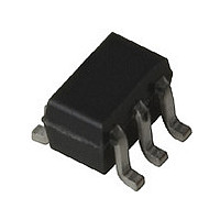
INA-31063 Avago Technologies US Inc., INA-31063 Datasheet - Page 7

INA-31063
Manufacturer Part Number
INA-31063
Description
Manufacturer
Avago Technologies US Inc.
Datasheet
1.INA-31063.pdf
(11 pages)
Specifications of INA-31063
Manufacturer's Type
RFIC Amplifier
Number Of Channels
1
Supply Current
13.5@3VmA
Frequency (max)
2.5GHz
Operating Supply Voltage (typ)
3V
Operating Supply Voltage (max)
6V
Package Type
SOT-363
Mounting
Surface Mount
Pin Count
6
Noise Figure (typ)
6.1@1900MHzdB
Lead Free Status / Rohs Status
Not Compliant
Available stocks
Company
Part Number
Manufacturer
Quantity
Price
Company:
Part Number:
INA-31063-TR1
Manufacturer:
INA
Quantity:
8 123
PCB Materials
Typical choices for PCB material
for low cost wireless applications
are FR-4 or G-10 with a thickness
of 0.025 (0.636 mm) or 0.031 inches
(0.787 mm). A thickness of 0.062
inches (1.574 mm) is the maximum
that is recommended for use with
this particular device. The use of a
thicker board material increases
the inductance of the plated
through vias used for RF grounding
and may deteriorate circuit
performance. Adequate grounding
is needed not only to obtain
maximum amplifier performance
but also to reduce any possibility
of instability.
Phase Reference Planes
The positions of the reference
planes used to measure
S-Parameters for this device are
shown in Figure 19. As seen in the
illustration, the reference planes
are located at the point where the
package leads contact the test
circuit.
Figure 19. Phase Reference Planes.
SOT-363 PCB Layout
The INA-31063 is packaged in the
miniature SOT-363 (SC-70)
surface mount package. A PCB
pad layout for the SOT-363
package is shown in Figure 20
(dimensions are in inches). This
layout provides ample allowance
for package placement by auto-
mated assembly equipment
without adding pad parasitics that
could impair the high frequency
performance of the INA-31063
TEST CIRCUIT
REFERENCE
PLANES
The layout that is shown with a
nominal SOT-363 package foot-
print superimposed on the PCB
pads for reference.
Figure 20. PCB Pad Layout for
INA-31063 (dimensions in inches).
Statistical Parameters
Several categories of parameters
appear within this data sheet.
Parameters may be described
with values that are either
“minimum or maximum,” “typi-
cal,” or “standard deviations.” The
values for parameters are based
on comprehensive product
characterization data, in which
automated measurements are
made on a large number of parts
taken from 3 non-consecutive
process lots of semiconductor
wafers. The data derived from
product characterization tends to
be normally distributed, e.g., fits
the standard “bell curve.” Param-
eters considered to be the most
important to system performance
are bounded by minimum or
maximum values. For the
INA-31063, these parameters are:
Power Gain ( |S21|
Device Current (I
guaranteed parameters is 100%
tested. Values for most of the
parameters in the table of Electri-
cal Specifications that are de-
scribed by typical data are the
mathematical mean ( ), of the
normal distribution taken from
the characterization data. For
0.035
0.026
0.016
d
2
). Each of these
), and the
0.075
parameters where measurements
or mathematical averaging may
not be practical, such as
S-parameters or Noise Param-
eters and the performance
curves, the data represents a
nominal part taken from the
“center” of the characterization
distribution. Typical values are
intended to be used as a basis for
electrical design.
To assist designers in optimizing
not only the immediate circuit
using the INA-31063, but to also
optimize and evaluate trade-offs
that affect a complete wireless
system, the standard deviation
( ) is provided for three of the
Electrical Specifications param-
eters (at 25 C) in addition to the
mean. The standard deviation is a
measure of the variability about
the mean. It will be recalled that a
normal distribution is completely
described by the mean and
standard deviation. Standard
statistics tables or calculations
provide the probability of a
parameter falling between any
two values, usually symmetrically
located about the mean. Referring
to Figure 21 for example, the
probability of a parameter being
between 1 is 68.3%; between
99.7%.
Figure 21. Normal Distribution.
2 is 95.4%; and between 3 is
-3
7
-2
-1
Parameter Value
68%
95%
99%
( ), typ
Mean
+1
+2
+3


