GP1UM287RKVF Sharp Microelectronics, GP1UM287RKVF Datasheet - Page 5
GP1UM287RKVF
Manufacturer Part Number
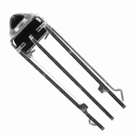
GP1UM287RKVF
Description
RECEIVER IR REM CTRL 5V 56.8KHZ
Manufacturer
Sharp Microelectronics
Datasheet
1.GP1UM287RKVF.pdf
(6 pages)
Specifications of GP1UM287RKVF
Sensing Distance
8.5m
B.p.f. Center Frequency
56.8kHz
Voltage - Supply
4.5 V ~ 5.5 V
Current - Supply
1.5mA
Orientation
Top View
Mounting Type
Through Hole
Lead Free Status / Rohs Status
Lead free / RoHS Compliant
Other names
425-2525


2. Use the light emitting unit (remote control transmitter), in consideration of performance, characteristics, operating conditions of
7. To avoid the electrostatic breakdown of IC, handle the unit under the condition of grounding with human body, soldering iron, etc.
1. When this infrared remote control detecting unit shall be adopted for wireless remote control, please use the following signal format .
(NEC code,RC-6code etc.)
3. Pay attention to a malfunction of the light detecting unit when the surface is stained with dust and refuse.
4. The shield case should be grounded on PCB pattern.
5. Do not apply unnecessary force to the terminal and the case.
6. Do not push the light detector surface (photodiode) from outside.
8. Do not use hole and groove set in the case of the light detecting unit for other purposes, since they are required to maintain the
9. External Circuit Examples (Mount the outer parts as near the unit as possible).
・ON signal time T
■ Precautions for Operation
・Total duty ratio D
Care must be taken not to touch the light detector surface.
(The area across the shield case and the GND terminal is internally non-conductive.)
The circuit constant is a example. It is difference from mounting equipment. Please select it by your mounting equipment.
This device has a transistor as protection element between V
Please be carefully not to apply exceeding the absolute maximum ratings of applying voltage and continuous high voltage spike
noise because there is cases that transistor will be short by secondary breakdown generally. In order to do difficultly, Please add CR
filter(47Ω(1/10W), 10μF or more)such as external circuit example above near V
light emitting device and the characteristics of the light detecting unit.
If it should be dirty, wipe off such dust and refuse with soft cloth so as to prevent scratch. In case some solvents are required, use
methyl alcohol, ethyl alcohol or isopropyl alcohol only.
Also, protect the light detecting unit against flux and others, since their deposition on the unit inside causes reduction of the
function, fading of markings such as the part number.
In setting R
specified performance.
In case the signal format of total duty and/or ON/OFF signal time dosen`t meet the conditions noted above, there is a
case that reception distance much reduces or output dose not appear.
1
and C
ON:
1
t
, use suitable values after considering under the real condition
(Emitting time t
t
1
200μs or more.
GND
V
V
CC
OUT
Σ
N=1
n
t
2
N
/ Transmitting time for 1 block T) : 40% or less.
C
Transmitting time for 1 block:T
O
+
t
3
D
t
=(
N=1
Σ
n
R
t
1
N
/T) ×100 (%)
CC
and GND to improve anti-static electricity proof.
5
GND
V
V
e
O
(Circuit parameters)
R
C
1=
1=
GP1UM26XK0VF/GP1UM27XK0VF Series
GP1UM28XK0VF/GP1UM28YK0VF Series
47Ω±5%
47μF
CC
T
.
t
ON
n
Sheet No.: OP06008
Related parts for GP1UM287RKVF
Image
Part Number
Description
Manufacturer
Datasheet
Request
R

Part Number:
Description:
IC FLASH 32MBIT 110NS 56SSOP
Manufacturer:
Sharp Microelectronics
Datasheet:

Part Number:
Description:
IC FLASH 16MBIT 100NS 56TSOP
Manufacturer:
Sharp Microelectronics
Datasheet:

Part Number:
Description:
IC FLASH 64MBIT 120NS 56TSOP
Manufacturer:
Sharp Microelectronics
Datasheet:

Part Number:
Description:
IC FLASH 16MBIT 90NS 48TSOP
Manufacturer:
Sharp Microelectronics
Datasheet:
Part Number:
Description:
IC SRAM 16KBIT 100NS 24DIP
Manufacturer:
Sharp Microelectronics
Datasheet:
Part Number:
Description:
IC SRAM 16KBIT 100NS 24SOP
Manufacturer:
Sharp Microelectronics
Datasheet:
Part Number:
Description:
IC SRAM 64KBIT 100NS 28DIP
Manufacturer:
Sharp Microelectronics
Datasheet:
Part Number:
Description:
IC SRAM 64KBIT 100NS 28SOP
Manufacturer:
Sharp Microelectronics
Datasheet:
Part Number:
Description:
IC SRAM 64KBIT 100NS 28SOP
Manufacturer:
Sharp Microelectronics
Datasheet:
Part Number:
Description:
IC SRAM 256KBIT 70NS 28DIP
Manufacturer:
Sharp Microelectronics
Datasheet:
Part Number:
Description:
IC FLASH 8MBIT 90NS 48TSOP
Manufacturer:
Sharp Microelectronics
Datasheet:
Part Number:
Description:
IC FLASH 8MBIT 85NS 40TSOP
Manufacturer:
Sharp Microelectronics
Datasheet:
Part Number:
Description:
IC FLASH 8MBIT 85NS 40TSOP
Manufacturer:
Sharp Microelectronics
Datasheet:
Part Number:
Description:
IC FLASH 16MBIT 90NS 48TSOP
Manufacturer:
Sharp Microelectronics
Datasheet:
Part Number:
Description:
IC FLASH 16MBIT 70NS 56TSOP
Manufacturer:
Sharp Microelectronics
Datasheet: