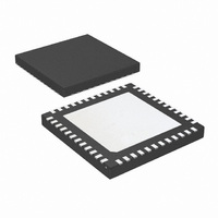
DS08MB200TSQX/NOPB National Semiconductor, DS08MB200TSQX/NOPB Datasheet - Page 2

DS08MB200TSQX/NOPB
Manufacturer Part Number
DS08MB200TSQX/NOPB
Description
IC MUX/BUFFER DUAL 800MBPS 48LLP
Manufacturer
National Semiconductor
Type
MUXr
Datasheet
1.DS08MB200TSQNOPB.pdf
(10 pages)
Specifications of DS08MB200TSQX/NOPB
Tx/rx Type
LVDS
Delay Time
1.0ns
Capacitance - Input
3.5pF
Voltage - Supply
3 V ~ 3.6 V
Current - Supply
275mA
Mounting Type
Surface Mount
Package / Case
48-LLP
Number Of Elements
3
Number Of Receivers
3
Number Of Drivers
3
Input Type
CMOS/TTL
Operating Supply Voltage (typ)
3.3V
Differential Input High Threshold Voltage
100mV
Diff. Input Low Threshold Volt
-100mV
Output Type
Repeater
Differential Output Voltage
500mV
Transmission Data Rate
800Mbps
Propagation Delay Time
2.5ns
Power Dissipation
5.2W
Operating Temp Range
-40C to 85C
Operating Temperature Classification
Industrial
Mounting
Surface Mount
Pin Count
48
Package Type
LLP
Lead Free Status / RoHS Status
Lead free / RoHS Compliant
Other names
*DS08MB200TSQX/NOPB
DS08MB200TSQX
DS08MB200TSQX
www.national.com
SWITCH SIDE DIFFERENTIAL INPUTS
SIA_0+
SIA_0−
SIA_1+
SIA_1−
SIB_0+
SIB_0−
SIB_1+
SIB_1−
LINE SIDE DIFFERENTIAL INPUTS
LI_0+
LI_0−
LI_1+
LI_1−
SWITCH SIDE DIFFERENTIAL OUTPUTS
SOA_0+
SOA_0−
SOA_1+
SOA_1−
SOB_0+
SOB_0−
SOB_1+
SOB_1−
LINE SIDE DIFFERENTIAL OUTPUTS
LO_0+
LO_0−
LO_1+
LO_1−
DIGITAL CONTROL INTERFACE
MUX_S0
MUX_S1
ENA_0
ENA_1
ENB_0
ENB_1
ENL_0
ENL_1
POWER
V
GND
N/C
DD
Pin Descriptions
Note 1: For interfacing LVDS outputs to CML or LVPECL compatible inputs, refer to the applications section of this datasheet.
Note 2: Note that the DAP on the backside of the LLP package is the primary GND connection for the device when using the LLP package.
Note 3: The LVDS outputs do not support a multidrop (BLVDS) environment. The LVDS output characteristics of the DS08MB200 device have been optimized
for point-to-point backplane and cable applications.
Name
Pin
2, 3, 46, 47
24, 25, 26,
6, 12, 37,
Number
LLP Pin
(Note 2)
1, 5, 23,
43, 48
30
29
19
20
28
27
21
22
40
39
10
34
33
15
16
32
31
17
18
42
41
38
11
36
13
35
14
45
44
9
7
8
4
I/O, Type
O, LVDS
O, LVDS
O, LVDS
O, LVDS
O, LVDS
O, LVDS
I, LVTTL
I, LVTTL
I, LVTTL
I, Power
I, Power
I, LVDS
I, LVDS
I, LVDS
I, LVDS
I, LVDS
I, LVDS
Switch A-side Channel 0 inverting and non-inverting differential inputs. LVDS, Bus LVDS, CML,
or LVPECL compatible.
Switch A-side Channel 1 inverting and non-inverting differential inputs. LVDS, Bus LVDS, CML,
or LVPECL compatible.
Switch B-side Channel 0 inverting and non-inverting differential inputs. LVDS, Bus LVDS, CML,
or LVPECL compatible.
Switch B-side Channel 1 inverting and non-inverting differential inputs. LVDS, Bus LVDS, CML,
or LVPECL compatible.
Line-side Channel 0 inverting and non-inverting differential inputs. LVDS, Bus LVDS, CML, or
LVPECL compatible.
Line-side Channel 1 inverting and non-inverting differential inputs. LVDS, Bus LVDS, CML, or
LVPECL compatible.
Switch A-side Channel 0 inverting and non-inverting differential outputs. LVDS compatible (Notes
1, 3).
Switch A-side Channel 1 inverting and non-inverting differential outputs. LVDS compatible (Notes
1, 3).
Switch B-side Channel 0 inverting and non-inverting differential outputs. LVDS compatible (Notes
1, 3).
Switch B-side Channel 1 inverting and non-inverting differential outputs. LVDS compatible (Notes
1, 3).
Line-side Channel 0 inverting and non-inverting differential outputs. LVDS compatible (Notes 1,
3).
Line-side Channel 1 inverting and non-inverting differential outputs. LVDS compatible (Notes 1,
3).
Mux Select Control Inputs (per channel) to select which Switch-side input, A or B, is passed
through to the Line-side.
Output Enable Control for Switch A-side and B-side outputs. Each output driver on the A-side and
B-side has a separate enable pin.
Output Enable Control for The Line-side outputs. Each output driver on the Line-side has a
separate enable pin.
V
Ground reference for LVDS and CMOS circuitry.
For the LLP package, the DAP is used as the primary GND connection to the device. The DAP
is the exposed metal contact at the bottom of the LLP-48 package. It should be connected to the
ground plane with at least 4 vias for optimal AC and thermal performance.
No Connect
DD
= 3.3V ±0.3V.
2
Description


