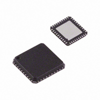
ADV7180BCPZ Analog Devices Inc, ADV7180BCPZ Datasheet - Page 38

ADV7180BCPZ
Manufacturer Part Number
ADV7180BCPZ
Description
IC VIDEO DECODER SDTV 40-LFCSP
Manufacturer
Analog Devices Inc
Type
Video Decoderr
Datasheet
1.ADV7180BSTZ.pdf
(116 pages)
Specifications of ADV7180BCPZ
Design Resources
Low Cost Differential Video Receiver Using ADA4851 Amplifier and ADV7180 Video Decoder (CN0060) Low Cost Video Multiplexer for Video Switching Using ADA4853-2 Op Amp with Disable Function (CN0076)
Applications
Digital Cameras, Mobile Phones, Portable Video
Voltage - Supply, Analog
1.71 V ~ 1.89 V
Voltage - Supply, Digital
1.65 V ~ 2 V
Mounting Type
Surface Mount
Package / Case
40-LFCSP
Resolution (bits)
10bit
Input Format
Analog
Output Format
Digital
Adc Sample Rate
57.27MSPS
Power Dissipation Pd
250mW
No. Of Input Channels
3
Supply Voltage Range
1.71V To 1.89V
Lead Free Status / RoHS Status
Lead free / RoHS Compliant
For Use With
EVAL-ADV7180LQEBZ - BOARD EVALUATION ADV7180EVAL-ADV7180LFEBZ - BOARD EVAL FOR ADV7180 LFCSP
Lead Free Status / RoHS Status
Lead free / RoHS Compliant, Lead free / RoHS Compliant
Available stocks
Company
Part Number
Manufacturer
Quantity
Price
Company:
Part Number:
ADV7180BCPZ
Manufacturer:
ADI
Quantity:
1 470
Company:
Part Number:
ADV7180BCPZ
Manufacturer:
AD
Quantity:
699
Part Number:
ADV7180BCPZ
Manufacturer:
ADI/亚德诺
Quantity:
20 000
Company:
Part Number:
ADV7180BCPZ-REEL
Manufacturer:
HP
Quantity:
600
Company:
Part Number:
ADV7180BCPZ-S
Manufacturer:
MAX
Quantity:
2 230
Part Number:
ADV7180BCPZ-S
Manufacturer:
ADI/亚德诺
Quantity:
20 000
ADV7180
CHROMA TRANSIENT IMPROVEMENT (CTI)
The signal bandwidth allocated for chroma is typically much
smaller than that for luminance. In the past, this was a valid way
to fit a color video signal into a given overall bandwidth because
the human eye is less sensitive to chrominance than to luminance.
The uneven bandwidth, however, may lead to visual artifacts in
sharp color transitions. At the border of two bars of color, both
components (luma and chroma) change at the same time (see
Figure 29). Due to the higher bandwidth, the signal transition
of the luma component is usually much sharper than that of the
chroma component. The color edge is not sharp and can be
blurred, in the worst case, over several pixels.
The chroma transient improvement block examines the input video
data. It detects transitions of chroma and can be programmed to
create steeper chroma edges in an attempt to artificially restore
lost color bandwidth. The CTI block, however, operates only
on edges above a certain threshold to ensure that noise is not
emphasized. Care has also been taken to ensure that edge
ringing and undesirable saturation or hue distortion are avoided.
Chroma transient improvements are needed primarily for
signals that have severe chroma bandwidth limitations. For
those types of signals, it is strongly recommended to enable
the CTI block via CTI_EN.
CTI_EN, Chroma Transient Improvement Enable,
Address 0x4D[0]
Setting CTI_EN to 0 disables the CTI block.
Setting CTI_EN to 1 (default) enables the CTI block.
CHROMA SIGNAL
DEMODULATED
LUMA SIGNAL
Figure 29. CTI Luma/Chroma Transition
SHARPENED CHROMA
TRANSITION AT THE
OUTPUT OF CTI
LUMA SIGNAL WITH A
TRANSITION, ACCOMPANIED
BY A CHROMA TRANSITION
ORIGINAL, SLOW CHROMA
TRANSITION PRIOR TO CTI
Rev. F | Page 38 of 116
CTI_AB_EN, Chroma Transient Improvement
Alpha Blend Enable, Address 0x4D[1]
The CTI_AB_EN bit enables an alpha blend function within
the CTI block. If set to 1, the alpha blender mixes the transient
improved chroma with the original signal. The sharpness of the
alpha blending can be configured via the CTI_AB[1:0] bits.
For the alpha blender to be active, the CTI block must be
enabled via the CTI_EN bit.
Setting CTI_AB_EN to 0 disables the CTI alpha blender.
Setting CTI_AB_EN to 1 (default) enables the CTI alpha-blend
mixing function.
CTI_AB[1:0], Chroma Transient Improvement Alpha
Blend, Address 0x4D[3:2]
The CTI_AB[1:0] controls the behavior of alpha blend circuitry
that mixes the sharpened chroma signal with the original one. It
thereby controls the visual impact of CTI on the output data.
For CTI_AB[1:0] to become active, the CTI block must be
enabled via the CTI_EN bit, and the alpha blender must be
switched on via CTI_AB_EN.
Sharp blending maximizes the effect of CTI on the picture but
may also increase the visual impact of small amplitude, high
frequency chroma noise.
Table 48. CTI_AB Function
CTI_AB[1:0]
00
01
10
11 (default)
CTI_C_TH[7:0], CTI Chroma Threshold, Address 0x4E[7:0]
The CTI_C_TH[7:0] value is an unsigned, 8-bit number specifying
how big the amplitude step in a chroma transition must be to be
steepened by the CTI block. Programming a small value into this
register causes even smaller edges to be steepened by the CTI
block. Making CTI_C_TH[7:0] a large value causes the block to
improve large transitions only.
The default value for CTI_C_TH[7:0] is 0x08, indicating the
threshold for the chroma edges prior to CTI.
Description
Sharpest mixing between sharpened and
original chroma signal
Sharp mixing
Smooth mixing
Smoothest alpha blend function


