MIKROE-415 mikroElektronika, MIKROE-415 Datasheet - Page 23

MIKROE-415
Manufacturer Part Number
MIKROE-415
Description
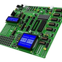
Development Boards & Kits - AVR EASYAVR6 DEVELOPMENT SYSTEM
Manufacturer
mikroElektronika
Datasheet
1.MIKROE-415.pdf
(28 pages)
Specifications of MIKROE-415
Tool Type
AVR Development Board
Interface Type
RS-232, USB, JTAG UART
Dimensions
265 mm x 220 mm
Operating Supply Voltage
9 V to 32 V
Lead Free Status / Rohs Status
Details
EasyAVR6 Development System
EasyAVR6 Development System
19.0.
19.0. Input/Output Ports
Along the right side of the development system, there are seven 10-pin connectors which are connected to the microcontroller’s I/O
ports. Some of the connector pins are directly connected to the microcontroller pins, whereas some of them are connected using
jumpers. DIP switches SW1-SW5 enable each connector pin to be connected to one pull-up/pull-down resistor. Whether port pins are
to be connected to a pull-up or pull-down resistor depends on the position of jumpers J1-J5.
Figure 19-4: PORTA connection schematic
Jumper for pull-up/pull-
down resistor selection
DIP switch to turn
on pull-up/pull-down
resistors for each pin
SW1: 1-8 = OFF
Jumper J1 in the pull-down position
Jumper J13 in the VCC position
Input/Output Ports
VCC
Figure 19-1: I/O ports
DIP40
PB0
PB1
PB2
PB3
PB4
PB5
PB6
PB7
RESET
VCC
GND
XTAL2
XTAL1
PD0
PD1
PD2
PD3
PD4
PD5
PD6
AVCC
AREF
GND
PC7
PC6
PC5
PC4
PC3
PC2
PC0
PD7
PA0
PA2
PA3
PA4
PA5
PA6
PA7
PC1
PA1
VCC
PA0
T1
VCC
PA1
T2
PA0
PA2
PA4
PA6
down
PORTA
pull
CN8
up
VCC
PA2
T3
PA1
PA3
PA5
PA7
J1 SW1
RN1
PA3
T4
PA4
T5
8x10K
PA5
T6
PA6
T7
Additional module
connected to PORTC
PA0
PA1
PA2
PA3
PA4
PA5
PA6
PA7
2x5 PORTB male
connector
PA7
T8
LD1
LD2
LD3
LD4
LD5
LD6
LD7
LD8
J18
R58
220R
VCC
RN13
8x4K7
Figure 19-3: J3 in the
pull-up position
Figure 19-2: J3 in the
pull-down position
J13
MikroElektronika
23


