MIKROE-415 mikroElektronika, MIKROE-415 Datasheet
MIKROE-415
Specifications of MIKROE-415


Related parts for MIKROE-415


MIKROE-415 Summary of contents
Page 1
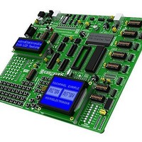
... EasyAVR6 All MikroElektronika´s development systems represent irreplaceable tools for programming and developing microcontroller-based devices. Carefully chosen components and the use of machines of the last generation for mounting and testing thereof are the best guarantee of high reliability of our devices. Due to simple design, a large number of add-on modules and ready to use examples, all our users, regardless of their experience, have the possibility to develop their project in a fast and effi ...
Page 2
... TO OUR VALUED CUSTOMERS I want to express my thanks to you for being interested in our products and for having confi dence in mikroElektronika. The primary aim of our company is to design and produce high quality electronic products and to constantly improve the performance thereof in order to better suit your needs. ...
Page 3
... A/D Converter Test Inputs........................................................................................................ 15 12.0. LEDs........................................................................................................................................ 16 13.0. Push Buttons........................................................................................................................... 17 14.0. Keyboards............................................................................................................................... 18 15.0. Alphanumeric 2x16 LCD ......................................................................................................... 19 16.0. On-Board 2x16 LCD with Serial Communication.................................................................... 20 17.0. 128x64 Graphic LCD................................................................................................................ 21 18.0. Touch Panel............................................................................................................................. 22 19.0. I/O Ports................................................................................................................................... 23 20.0. Port Expander (Additional I/O Ports)........................................................................................ 25 3 MikroElektronika ...
Page 4
... Numerous on-board modules, such as 128x64 graphic LCD, alphanumeric The AVRfl ash™ program provides a complete list of all supported microcontrollers. The latest version of this program with updated list of supported microcontrollers can be downloaded from our website www.mikroe.com Package contains: Development board: ...
Page 5
... Touch panel connector 19. MENU keypad 20. Keypad 4x4 21. Push buttons to simulate digital inputs 22. Logic state selector 23. Protective resistor ON/OFF jumper 24. Reset button 25. 35 LEDs to indicate pins’ logic state 26. DS1820 temperature sensor socket 27 Alphanumeric LCD contrast adjustment 28. Alphanumeric LCD connector 29. RS-232 communication connector MikroElektronika ...
Page 6
... Follow the instructions for installing USB drivers and the AVRfl ash program provided in the relevant manuals not possible to program AVR microcontrollers without having these devices installed fi rst. In case that you already have some of the MikroElektronika’s compilers installed on your PC, there is no need to reinstall the AVRfl ash program as it will be automatically installed along with the compiler. ...
Page 7
... CLK Pin PB3 is fed with a clock signal from the on-board oscillator VCC Pin is connected to VCC J11 PC7 PC7 is an I/O pin CLK Pin PB6 is fed with a clock signal from the on-board oscillator J20 PB6 PB6 is an I/O pin 3 7 Function 4 MikroElektronika ...
Page 8
... Figure 3-2: The principle of programmer’s operation NOTE: For more information on the AVRprog programmer refer to the relevant manual provided in the EasyAVR6 development system package. MikroElektronika EasyAVR6 Development System EasyAVR6 Development System Compiling program Bin. 1110001001 ...
Page 9
... DIP28 package During the programming, a multiplexer disconnects the microcontroller pins used for programming from the rest of the board and connects them to the AVRprog programmer. After the programming is complete, these pins are disconnected from the programmer and may be used as input/output pins. MikroElektronika 9 ...
Page 10
... Its maximum value depends on the maximum operating frequency of the microcontroller. Quartz crystal X2 plugged into the appropriate socket, which enables easily replaced Figure 6-1: Oscillator MikroElektronika EasyAVR6 Development System EasyAVR6 Development System Figure 5-2: JTAGICE mkII connected to the development system R64 VCC 1M ...
Page 11
... Side view 0.22 Top view U10 L2 SWC DRVC 220uH SWE IPK Vin CT GND CMPR C8 D7 MC34063A 220pF MBRS140T3 R56 R55 Side view Side view POWER SUPPLY switch OFF ON VCC-5V VCC-USB 10uF 330uF + Side view MikroElektronika 11 VCC LD42 POWER R14 2K2 ...
Page 12
... SW9: RX=PB2, TX=PB3 = ON RS232 SUB Bottom view Figure 8-2: RS-232 module schematic NOTE: Make sure that your microcontroller is provided with the USART module not necessarily integrated in all AVR microcontrollers. MikroElektronika RS-232 connector Figure 8-1: RS-232 module VCC C28 C1+ VCC 100nF 100nF ...
Page 13
... Figure 9-1: USB UART Figure 9-2: USB UART module (J16 and J17 are module (J16 and J17 are not placed) placed) Jumpers J16 and J17 are placed Figure 9-3: USB UART module and microcontroller connection schematic USB connector 13 MikroElektronika ...
Page 14
... Figure 10- the connector (1-wire com- left-hand position (1-wire munication is not used) communication the PA4 pin) Jumper J9 set in the PA4 position Figure 10-4: 1-wire communication connection schematic MikroElektronika Figure 10- the right-hand position (1-wire through communication through the PB2 pin) EasyAVR6 Development System ...
Page 15
... VCC VCC GND J12 PB0 PA0 R63 PB1 PA1 P1 10K PB3 PA2 220R PB2 PA3 PA7 PA4 DIP14 10K Top view VCC J12 PB0 P A0 R63 PB1 PA1 P1 10K P B2 PA2 220R GND VCC VCC 10K Top view DIP 0 2 MikroElektronika 15 ...
Page 16
... VCC VCC GND XTAL2 XTAL1 PD0 PD1 PD2 PD3 PD4 PD5 PD6 DIP40 Figure 12-2: LED diodes and PORTA connection schematic MikroElektronika Notch indicating the SMD LED cathode Microcontroller MCU PA0 LD1 PA0 PA1 PA2 PA1 LD2 PA3 PA4 PA2 LD3 ...
Page 17
... PC1 PC0 PD5 PD6 PD7 DIP40 Figure 13-2: PORTA push buttons connection schematic Figure 13-1: Push buttons used for simulating digital inputs VCC PA7 PA6 PA5 PA4 PA3 5V 0V VCC J13 5V 0V VCC J13 PA2 PA1 PA0 R58 J18 220R MikroElektronika 17 ...
Page 18
... Jumper J13 is in the VCC position. Pins PC0, PC1, PC2 and PC3 are connected to pull-down resis- tors through DIP switch SW3 Figure 14-4: Keypads (4x4 and MENU) and microcontroller connection schematic MikroElektronika PC7 PC6 PC5 PC4 "1" PC3 "1" PC2 "1" PC1 " ...
Page 19
... Figure 15-3: Alphanumeric 2x16 LCD connection schematic LCD Connector for alphanumeric LCD Contrast adjustment potentiometer VCC P7 PD3 10K PD2 PD7 PD6 PD5 PD4 VCC CN7 1 LCD Display LCD Display 4-bit mode 4-bit mode Figure 15-2: 2x16 LCD SW10 Top view DISP-BCK VCC R43 10 MikroElektronika 19 ...
Page 20
... PD1 PC4 PD2 PC3 PD3 PC2 PD4 PC1 PC0 PD5 PD6 PD7 DIP40 Figure 16-2: On-board 2x16 LCD connection schematic MikroElektronika with Serial Communication SW9 LCD Display LCD Display COG 2x16 COG 2x16 PE-INTA PD2 PD3 PE-INTB SW7 PB5 SPI- MOSI ...
Page 21
... PD1 PC4 PC3 PD2 PD3 PC2 PC1 PD4 PD5 PC0 PD6 PD7 DIP40 Figure 17-3: GLCD connection schematic Contrast adjustment potentiometer GLCD connector Touch panel connector Top view VCC VCC 1 Figure 17-2: GLCD connector SW10 P6 10K DISP-BCK VCC R28 10 CN6 20 MikroElektronika 21 ...
Page 22
... Figure 1. Plug the cable into the connector, as shown in Figure 2, and press it easily fi t the connector, as shown in Figure 3. Now you can plug a GLCD into the appropriate connector as shown in Figure 4. NOTE: LEDs and pull-up/pull-down resistors on the PORTA port must be turned off when using a touch panel. MikroElektronika 3 VCC-MCU 20 ...
Page 23
... PORTB male connector Figure 19- the pull-down position Additional module connected to PORTC Figure 19- the pull-up position PA0 LD1 RN13 PA1 LD2 PA2 LD3 8x4K7 PA3 LD4 PA4 LD5 PA5 LD6 PA6 LD7 PA7 LD8 VCC J13 PA6 PA7 R58 J18 220R T7 T8 MikroElektronika 23 ...
Page 24
... PD4 PD5 PC0 PD6 PD7 DIP40 Figure 19-6: Jumper J1 in pull-up and J13 in pull-down position VCC VCC up pull J1 J13 down Figure 19-7: Jumpers J1 and J13 in the same position MikroElektronika VCC RN1 8x10K J1 SW1 VCC J13 R58 PA0 J18 220R 5V 0V VCC ...
Page 25
... They are also used to provide the port expander’s pins A2, A1 and A0 with a logic logic 0. Jumpers J19 are set in the Down position (logic 0) by Parallel default. input 8bit PORT1 Figure 20-2: DIP switches SW6 and SW7 when port expander is enabled MikroElektronika 25 ...
Page 26
... SW6: CS#=PB1, RST=PB2, SCK = PB7 SW7: PB6 =MISO, PB5=MOSI Jumpers J14 and J15 in the pull-up position Figure 20-4: Port expander connection schematic MikroElektronika EasyAVR6 Development System EasyAVR6 Development System ...
Page 27
... HIGH RISK ACTIVITIES The products of MikroElektronika are not fault – tolerant nor designed, manufactured or intended for use or resale as on – line control equipment in hazardous environments requiring fail – safe performance, such as in the operation of nuclear facilities, aircraft navigation or communication systems, air traffi c control, direct life support machines or weapons systems in which the failure of Software could lead directly to death, personal injury or severe physical or environmental damage (‘ ...
Page 28
...