MIKROE-413 mikroElektronika, MIKROE-413 Datasheet
MIKROE-413
Specifications of MIKROE-413


Related parts for MIKROE-413


MIKROE-413 Summary of contents
Page 1
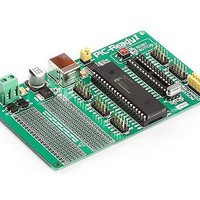
... PIC-Ready1 All Mikroelektronika’s development systems feature a large number of peripheral modules expanding microcontroller’s range of application and making the process of program testing easier. In addition to these modules also possible to use numerous additional modules linked to the development system through the I/O port connectors. Some of these additional modules can operate as stand-alone devices without being connected to the microcontroller. ™ ...
Page 2
... CN6 pins; place jumpers J1 and J2. The Bootloader software is integrated in all Mikroelektronika’s compilers. It communicates with the microcontroller via serial UART communication. The Bootloader .hex code is loaded into the microcontroller by using the PICFlash programmer and is necessary for loading ...
Page 3
... Pads that may be used as a proto board Figure 3: PIC-Ready1 additional board connected to a USB cable Jumpers J1 and J2 must be placed when the .hex code is loaded by using the bootloader software When the PICFlash programmer is not used, jumpers should be placed over the CN6 connector pins MikroElektronika ...
Page 4
... Figure 4: Additional board connection schematics MikroElektronika ...
Page 5
... The Bootloader software is integrated in all Mikroelektronika’s compilers used to load a .hex code into the microcontroller that already has the Bootloader .hex code loaded. In order to open the mikroBootloader window necessary to select the mikroBootloader option from the Tools menu within the compiler’s main window. The first thing you should do after that is to select the port to be used for connecting the additional board ...
Page 6
... MikroElektronika ...