MIKROE-604 mikroElektronika, MIKROE-604 Datasheet
MIKROE-604
Specifications of MIKROE-604


Related parts for MIKROE-604


MIKROE-604 Summary of contents
Page 1
... Serial Ethernet2 All Mikroelektronika’s development systems feature a large number of peripheral modules expanding microcontroller’s range of application and making the process of program testing easier. In addition to these modules also possible to use numerous additional modules linked to the development system through the I/O port connectors. Some of these additional modules can operate as stand-alone devices without being connected to the microcontroller. ™ ...
Page 2
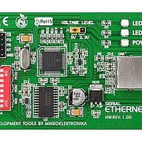
... J1 should be placed in the 3.3V position. The RJ45 connector CN5 is used to establish connection between the additional board and Ethernet network. A LED marked POWER indicates whether the additional board is turned on or off. The additional board uses LEDs marked LEDA and LEDB to indicate data transfer through the Ethernet network. MikroElektronika ...
Page 3
... EasyAVR, Easy8051 Position of switches on DIP switch SW1 for appropriate development system Table 1 Figure 2: Dimensions of the Serial Ethernet2 additional board MISO Easy dsPIC, Easy 24-33 EasyPIC, EasyLV-18F, LV18F, BigPIC EasyPIC, EasyLV-18F, LV18F, Easy 24-33, BigPIC, EasyAVR, EasyAVR, Easy8051 MOSI Easy dsPIC Easy8051 MikroElektronika ...
Page 4
... Figure 3: Serial Ethernet2 board connection schematic MikroElektronika ...
Page 5
... Figure 4: Serial Ethernet2 connected to a development system MikroElektronika ...
Page 6
... MikroElektronika ...