MIKROE-413 mikroElektronika, MIKROE-413 Datasheet - Page 2
MIKROE-413
Manufacturer Part Number
MIKROE-413
Description
Development Boards & Kits - PIC / DSPIC PIC-READY1 28-40 PIN PROTOTYPE BOARD
Manufacturer
mikroElektronika
Datasheet
1.MIKROE-413.pdf
(6 pages)
Specifications of MIKROE-413
Tool Type
PIC Ready Board
Interface Type
USB, IDC10, UART
Operating Supply Voltage
8 V to 16 V
Processor Series
PIC16F
Processor To Be Evaluated
PIC16F887
Lead Free Status / Rohs Status
Details


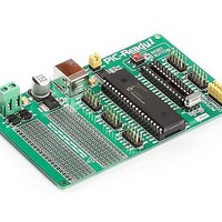
PIC-Ready1 Additional Board
The PIC-Ready1 additional board enables a .hex code to be quickly and easily loaded into PIC microcontrollers by using the PICFlash
programmer or the bootloader software. The additional board is supplied with two sockets for PIC microcontrollers in DIP40 and DIP28
package, 2x5 male connectors connected to the microcontroller pins, pads, srew terminal for power supply, USB connector and reset
button.
Figure 1: PIC-Ready1 additional board
The microcontroller placed on the additional board may be programmed with the PICFlash programmer or the bootloader software.
When the process of programming is performed with the PICFlash programmer, it is necessary to:
1. remove jumpers from the 2x5 male connector CN6 (PICFlash connector) provided on the development board;
2. link a 2x5 male connector on the PICFlash programmer with a 2x5 female connector on the development board, Figure 2; and
3. connect the PICFlash programmer to a PC, after which the process of loading .hex code into the microcontroller may start.
When this way of programming applies, it is not necessary to provide an external power supply as the board is powered by a PC
through the PICFlash programmer.
The Bootloader software enables the .hex code to be loaded into the microcontroller that has the bootloader .hex code loaded. Before
the programming process starts, it is necessary to:
1. provide the additional board with the power supply (8-16V AC/DC) via the CN8 connector;
2. connect the additional board to a PC via a USB cable; and
3. place jumpers on the 2x5 male connector CN6 pins; place jumpers J1 and J2.
The Bootloader software is integrated in all Mikroelektronika’s compilers. It communicates with the microcontroller via serial UART
communication. The Bootloader .hex code is loaded into the microcontroller by using the PICFlash programmer and is necessary for
loading .hex code into the microcontroller by using the bootloader software. Some microcontrollers get the bootloader .hex file in the
Example folder along with other examples for PIC compilers (for example, C:\Program Files\Mikroelektronika\mikroC PRO for PIC\
Examples\Other\Bootloader). When the .hex code loading is complete, it is necessary to reset the microcontroller by pressing the
Reset button.
In addition to the .hex code loading by the bootloader software, the USB connector supplied on the additional board can also be
used to enable connection between the microcontroller and other devices that use serial UART communication. Jumpers J1 and J2
should be placed when using the USB connector for UART communication. The additiotal board may also serve as a proto board as it
features pads used to connect components to be employed for making a prototype device. The 2x5 male connector placed next to the
DIP sockets enables easy access to the microcontroller pins. Each connector is linked to one microcontroller port (PORTA, PORTB,
PORTC, PORTE and PORTD).
MikroElektronika
Related parts for MIKROE-413
Image
Part Number
Description
Manufacturer
Datasheet
Request
R

Part Number:
Description:
Daughter Cards & OEM Boards SERIAL ETHERNET 2 ADAPTER BOARD
Manufacturer:
mikroElektronika
Datasheet:

Part Number:
Description:
Development Boards & Kits - AVR EASYAVR6 DEVELOPMENT SYSTEM
Manufacturer:
mikroElektronika
Datasheet:

Part Number:
Description:
Daughter Cards & OEM Boards RS485 (ADM485) ADAPTER BOARD
Manufacturer:
mikroElektronika

Part Number:
Description:
Daughter Cards & OEM Boards EASYCONNECT2 ADAPTER BOARD
Manufacturer:
mikroElektronika

Part Number:
Description:
Daughter Cards & OEM Boards SMARTPROTO PROTO ADAPTER BOARD
Manufacturer:
mikroElektronika

Part Number:
Description:
Daughter Cards & OEM Boards CAN SPI (MCP2551) TRANSCEIVER BOARD
Manufacturer:
mikroElektronika

Part Number:
Description:
Development Boards & Kits - PIC / DSPIC BIGPIC6 PROTO PROTOTYPE BOARD
Manufacturer:
mikroElektronika

Part Number:
Description:
Sockets & Adapters GLCD 240x128 SERIAL ADAPTER BOARD
Manufacturer:
mikroElektronika

Part Number:
Description:
Daughter Cards & OEM Boards ACCEL 3-AXIS ADAPTER BOARD
Manufacturer:
mikroElektronika

Part Number:
Description:
Daughter Cards & OEM Boards 3.3V VOLTAGE REGULATOR BOARD
Manufacturer:
mikroElektronika

Part Number:
Description:
Daughter Cards & OEM Boards USB UART 2 ADAPTER BOARD
Manufacturer:
mikroElektronika

Part Number:
Description:
Development Boards & Kits - PIC / DSPIC LV24-33 V6 DEVELOPMENT SYSTEM
Manufacturer:
mikroElektronika

Part Number:
Description:
Microcontroller Modules MCU CARD LV-32MX V6 100P PIC32MX460F512L
Manufacturer:
mikroElektronika

Part Number:
Description:
Microcontroller Modules MCU CARD BIGAVR6 100P W/ ATMEGA2560
Manufacturer:
mikroElektronika

Part Number:
Description:
Bluetooth / 802.15.1 Modules BLUETOOTH 2 STICK ADAPTER BOARD
Manufacturer:
mikroElektronika
Datasheet: