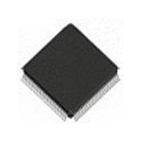
IDT82V2084PF IDT, Integrated Device Technology Inc, IDT82V2084PF Datasheet - Page 39

IDT82V2084PF
Manufacturer Part Number
IDT82V2084PF
Description
IC LIU T1/J1/E1 4CH 128-TQFP
Manufacturer
IDT, Integrated Device Technology Inc
Type
Line Interface Units (LIUs)r
Datasheet
1.IDT82V2084PFG8.pdf
(75 pages)
Specifications of IDT82V2084PF
Protocol
E1
Voltage - Supply
3.13 V ~ 3.47 V
Mounting Type
Surface Mount
Package / Case
128-TQFP, 128-VQFP
Screening Level
Industrial
Mounting
Surface Mount
Package Type
TQFP
Operating Temperature (min)
-40C
Operating Temperature (max)
85C
Lead Free Status / RoHS Status
Contains lead / RoHS non-compliant
Number Of Drivers/receivers
-
Lead Free Status / RoHS Status
Not Compliant, Contains lead / RoHS non-compliant
Other names
82V2084PF
Available stocks
Company
Part Number
Manufacturer
Quantity
Price
Company:
Part Number:
IDT82V2084PF
Manufacturer:
IDT, Integrated Device Technology Inc
Quantity:
10 000
Company:
Part Number:
IDT82V2084PF8
Manufacturer:
IDT, Integrated Device Technology Inc
Quantity:
10 000
Company:
Part Number:
IDT82V2084PFG
Manufacturer:
IDT
Quantity:
650
Company:
Part Number:
IDT82V2084PFG
Manufacturer:
IDT, Integrated Device Technology Inc
Quantity:
10 000
Part Number:
IDT82V2084PFG
Manufacturer:
IDT
Quantity:
20 000
Company:
Part Number:
IDT82V2084PFG8
Manufacturer:
IDT, Integrated Device Technology Inc
Quantity:
10 000
QUAD CHANNEL T1/E1/J1 LONG HAUL/SHORT HAUL LINE INTERFACE UNIT
Table-33 TCF2: Transmitter Configuration Register 2
Table-34 TCF3: Transmitter Configuration Register 3
Table-35 TCF4: Transmitter Configuration Register 4
SAMP[3:0]
WDAT[6:0]
SCAL[5:0]
Symbol
Symbol
Symbol
UI[1:0]
DONE
RW
-
-
(R/W, Address = 04H,44H,84H,C4H)
(R/W, Address = 05H,45H,85H,C5H)
(R/W, Address = 06H,46H,86H,C6H)
7-6
5-0
5-4
3-0
6-0
Bit
Bit
Bit
7
6
7
0000000
Default
Default
100001
Default
0000
00
00
0
0
0
Reserved
SCAL specifies a scaling factor to be applied to the amplitude of the user-programmable arbitrary pulses which is
to be transmitted if needed. The default value of SCAL[5:0] is ‘100001’. Refer to
trary
= 110110: default value for T1 0~133 ft, T1 133~266 ft, T1 266~399 ft, T1 399~533 ft, T1 533~655 ft, J1 0~655 ft,
= 010001: default value for DS1 -7.5 dB LBO. One step change of this value results in 6.25% scaling up/down
= 001000: default value for DS1 -15.0 dB LBO. One step change of this value results in 12.5% scaling up/down
= 000100: default value for DS1 -22.5 dB LBO. One step change of this value results in 25% scaling up/down
= 100001: default value for E1 75 Ω and 120 Ω. One step change of this value results in 3% scaling up/down
After ‘1’ is written to this bit, a read or write operation is implemented.
This bit selects read or write operation
= 0: write to RAM
= 1: read from RAM
These bits specify the unit interval address. There are 4 unit intervals.
= 00: UI address is 0 (The most left UI)
= 01: UI address is 1
= 10: UI address is 2
= 11: UI address is 3
These bits specify the sample address. Each UI has 16 samples.
= 0000: sample address is 0 (The most left Sample)
= 0001: sample address is 1
= 0010: sample address is 2
......
= 1110: sample address is 14
= 1111: sample address is 15
Reserved
In Indirect Write operation, the WDAT[6:0] will be loaded to the pulse template RAM, specifying the amplitude of
the Sample.
After an Indirect Read operation, the amplitude data of the Sample in the pulse template RAM will be output to the
WDAT[6:0].
DS1 0dB LBO. One step change of this value results in 2% scaling up/down against the pulse amplitude.
against the pulse amplitude.
against the pulse amplitude.
against the pulse amplitude.
against the pulse amplitude.
Waveform.
39
Description
Description
Description
3.2.3.3 User-Programmable Arbi-
TEMPERATURE RANGES
INDUSTRIAL


