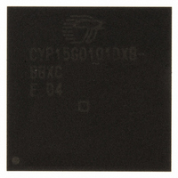
CYP15G0101DXB-BBXC Cypress Semiconductor Corp, CYP15G0101DXB-BBXC Datasheet - Page 15

CYP15G0101DXB-BBXC
Manufacturer Part Number
CYP15G0101DXB-BBXC
Description
IC TXRX HOTLINK 100-LBGA
Manufacturer
Cypress Semiconductor Corp
Series
HOTlink II™r
Type
Transceiverr
Specifications of CYP15G0101DXB-BBXC
Package / Case
100-LBGA
Protocol
Fibre Channel
Voltage - Supply
3.135 V ~ 3.465 V
Mounting Type
Surface Mount
Product
PHY
Data Rate
1500 MBd
Supply Voltage (max)
3.465 V
Supply Voltage (min)
3.135 V
Supply Current
0.5 A
Maximum Operating Temperature
+ 70 C
Minimum Operating Temperature
0 C
Mounting Style
SMD/SMT
Number Of Channels
1
Lead Free Status / RoHS Status
Lead free / RoHS Compliant
For Use With
CYP15G0101DX-EVAL - EVAL BRD FOR HOTLINK II
Number Of Drivers/receivers
-
Lead Free Status / Rohs Status
Lead free / RoHS Compliant
Other names
428-2920
CYP15G0101DXB-BBXC
CYP15G0101DXB-BBXC
Available stocks
Company
Part Number
Manufacturer
Quantity
Price
Company:
Part Number:
CYP15G0101DXB-BBXC
Manufacturer:
MURATA
Quantity:
260 000
Company:
Part Number:
CYP15G0101DXB-BBXC
Manufacturer:
CYPRESS
Quantity:
206
Company:
Part Number:
CYP15G0101DXB-BBXC
Manufacturer:
Cypress Semiconductor Corp
Quantity:
10 000
Part Number:
CYP15G0101DXB-BBXC
Manufacturer:
CYPRESS/赛普拉斯
Quantity:
20 000
When TXMODE[1] = HIGH (TX modes 6, 7, and 8), the
generation of the Word Sync Sequence becomes an interruptible
operation. In TX Mode 6, this sequence is started as soon as the
TXCT[1:0] = 11 condition is detected on the channel. In order for
the sequence to continue, the TXCT[1:0] inputs must be sampled
as 00 for the remaining 15 characters of the sequence. If at any
time a sample period exists where TXCT[1:0] 00, the Word
Sync Sequence is terminated, and a character representing the
data and control bits is generated by the encoder. This resets the
Word Sync Sequence state machine such that it will start at the
beginning of the sequence at the next occurrence of
TXCT[1:0] = 11.
When parity checking is enabled and TXMODE[1] = HIGH, all
characters (including those in the middle of a Word Sync
Sequence) must have correct parity. The detection of a character
with incorrect parity during a Word Sync Sequence (regardless
of the state of TXCT[1:0]) will interrupt that sequence and force
generation of a C0.7 SVS character. Any interruption of the Word
Sync Sequence causes the sequence to terminate.
When TXCKSEL = LOW, the input register for the transmit
channel is clocked by REFCLK.
MID, the input register for the transmit channel is clocked with
TXCLK.
TX Mode 4—Atomic Word Sync and SCSEL Control of
Word Sync Sequence Generation
When configured in TX Mode 4, the SCSEL input is captured
along with the TXCT[1:0] data control inputs. These bits combine
to control the interpretation of the TXD[7:0] bits and the
characters generated by them. These bits are interpreted as
listed in
Table 6. TX Modes 4 and 7 Encoding
TX Mode 4 also supports an Atomic Word Sync Sequence.
Unlike TX Mode 3, this sequence is started when both SCSEL
and TXCT[0] are sampled HIGH. With the exception of the
combination of control bits used to initiate the sequence, the
generation and operation of this Word Sync Sequence is the
same as that documented for TX Mode 3.
Document Number: 38-02031 Rev. *L
Note
15. When REFCLK is configured for half-rate operation (TXRATE
X
0
0
1
REFCLK.
X
X
0
1
Table
0
1
1
1
6.
Encoded data character
K28.5 fill character
Special character code
16-character Word Sync Sequence
Characters Generated
[15]
When TXCKSEL = HIGH or
=
HIGH), this input is sampled (or the outputs change) relative to both the rising and falling edges of
TX Mode 5—Atomic Word Sync, No SCSEL
When configured in TX Mode 5, the SCSEL signal is not used.
The TXCT[1:0] inputs control the characters generated by the
channel. The specific characters generated by these bits are
listed in
Table 7. TX Modes 5 and 8 Encoding
TX Mode 5 also has the capability of generating an Atomic Word
Sync Sequence. For the sequence to be started, the TXCT[1:0]
inputs must both be sampled HIGH. The generation and
operation of this Word Sync Sequence is the same as that
documented for TX Mode 3.
Transmit BIST
The transmit channel contains an internal pattern generator that
can be used to validate both device and link operation. This
generator is enabled by the BOE[1] signal, as listed in
(when the BISTLE latch enable input is HIGH). When enabled,
a register in the transmit channel becomes a signature pattern
generator by logically converting to a linear feedback shift
register (LFSR). This LFSR generates a 511-character
sequence that includes all data and special character codes,
including the explicit violation symbols. This provides a
predictable yet pseudo-random sequence that can be matched
to an identical LFSR in the attached Receiver. If the receive
channel is configured for REFCLK clocking (RXCKSEL = LOW),
each pass is preceded by a 16-character Word Sync Sequence
to allow elasticity buffer alignment and management of
clock-frequency variations.
When the BISTLE signal is HIGH, if the BOE[1] input is LOW, the
BIST generator in the transmit channel is enabled (and if
BOE[0] = LOW the BIST checker in the receive channel is
enabled). When BISTLE returns LOW, the values of the
BOE[1:0] signals are captured in the BIST enable latch. These
values remain in the BIST enable latch until BISTLE is returned
high to open the latch again. A device reset (TRSTZ sampled
LOW), also presets the BIST enable latch to disable BIST on
both the transmit and receive channels.
All data and data-control information present at the TXD[7:0] and
TXCT[1:0] inputs are ignored when BIST is active on the transmit
channel.
X
X
X
X
0
0
1
1
Table
0
1
0
1
7.
Encoded data character
K28.5 fill character
Special character code
16-character Word Sync Sequence
Characters Generated
CYW15G0101DXB
CYP15G0101DXB
CYV15G0101DXB
Page 15 of 44
Table 8
[+] Feedback


