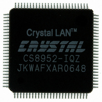
CS8952-IQZ Cirrus Logic Inc, CS8952-IQZ Datasheet - Page 20

CS8952-IQZ
Manufacturer Part Number
CS8952-IQZ
Description
IC TXRX 100/10 PHY 100TQFP
Manufacturer
Cirrus Logic Inc
Type
Transceiverr
Datasheet
1.CS8952-IQZ.pdf
(81 pages)
Specifications of CS8952-IQZ
Package / Case
100-TQFP, 100-VQFP
Protocol
MII
Voltage - Supply
4.75 V ~ 5.25 V
Mounting Type
Surface Mount
Minimum Operating Temperature
0 C
Mounting Style
SMD/SMT
Product
Ethernet Transceivers
Number Of Transceivers
1
Standard Supported
100BASE-FX or 100BASE-TX or 10BASE-T
Data Rate
10 Mbps or 100 Mbps
Supply Voltage (max)
6 V
Supply Voltage (min)
- 0.3 V
Supply Current (max)
+/- 10 mA
Maximum Operating Temperature
+ 70 C
Lead Free Status / RoHS Status
Lead free / RoHS Compliant
Number Of Drivers/receivers
-
Lead Free Status / Rohs Status
Lead free / RoHS Compliant
Other names
598-1208
Available stocks
Company
Part Number
Manufacturer
Quantity
Price
Company:
Part Number:
CS8952-IQZ
Manufacturer:
CIRRUS
Quantity:
560
Company:
Part Number:
CS8952-IQZ
Manufacturer:
CIRRUS
Quantity:
70
Part Number:
CS8952-IQZ
Manufacturer:
CRYSTAL
Quantity:
20 000
Company:
Part Number:
CS8952-IQZR
Manufacturer:
Cirrus Logic Inc
Quantity:
10 000
rupt signal to the controller when a change of state
has occurred in the CS8952, eliminating the need
for the system to poll the CS8952 for state changes.
The RX_EN signal allows the receiver outputs to
be electrically isolated. The ISODEF pin controls
the value of register bit ISOLATE in the Basic
Mode Control Register (address 00h) which in turn
electrically isolates the CS8952's MII data path.
3.1
The following sections describe the four major op-
erating modes of the CS8952:
The choice of operating speed (10 Mb/s versus
100 Mb/s) is made using the auto-negotiation input
pins (AN0, AN1) and/or the auto-negotiation MII
registers. The auto-negotiation capability also is
used to select a duplex mode (full or half duplex).
Both speed and duplex modes can either be forced
or negotiated with the far-end link partner.
The digital interface mode (MII, repeater, or
10BASE-T serial) is selected by input pins
BPALIGN, BP4B5B and 10BT_SER as shown in
Table 1. Speed and duplex selection are made
through the AN[1:0] pins as shown in Table 5.
CrystalLAN™ 100BASE-X and 10BASE-T Transceiver
DS206F1
100BASE-X MII
10BASE-T MII
Operating Mode BPALIGN BP4B5B 10BT_SER
-
-
-
-
100BASE-X MII Modes (TX and FX)
100BASE-X Repeater Modes
10BASE-T MII Mode
10BASE-T Serial Mode
Major Operating Modes
DATA (Note 1)
Name
0
1
Table 1.
0
0
5-bit Symbol
DATA and CONTROL Codes (RX_ER = 0 or TX_ER = 0)
01001
11110
0
0
4-bit Nibble
0000
0001
0
0
3.1.1
The CS8952 provides an IEEE 802.3-compliant
MII interface. Data is transferred across the MII in
four-bit parallel (nibble) mode. TX_CLK and
RX_CLK are nominally 25 MHz for 100BASE-X.
The 100BASE-X mode includes both the TX and
FX modes, as determined by pin BPSCR (bypass
scrambler), or the BPSCR bit (bit 13) in the Loop-
back, Bypass, and Receiver Error Mask Register
(address 18h). In FX mode, an external optical
module is connected to the CS8952 via pins
TX_NRZ+, TX_NRZ-, RX_NRZ+, RX_NRZ-,
SIGNAL+, and SIGNAL-. In FX mode, the MLT-
3/NRZI conversion blocks and the scrambler/de-
scrambler are bypassed.
3.1.1.1
In 100BASE-X modes, 4-bit nibble transmit data is
encoded into 5-bit symbols for transmission onto
the media as shown in Tables 2 and 3. The encod-
ing is necessary to allow data and control symbols
to be sent consecutively along the same media
transparent to the MAC layer. This encoding caus-
es the symbol rate transmitted across the wire (125
symbols/second) to be greater than the actual data
rate of the system (100 symbols/second).
100BASE-X
Repeater
10BASE-T Serial
Operating Mode BPALIGN BP4B5B 10BT_SER
100BASE-X MII Application (TX
and FX)
Symbol Encoding and Decoding
Comments
Don’t
Care
Table 1.
1
0
Don’t
Don’t
Care
Care
1
CS8952
0
0
1
20


