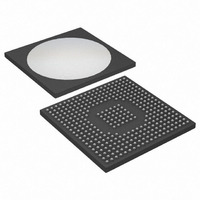
DS31412N Maxim Integrated Products, DS31412N Datasheet - Page 7

DS31412N
Manufacturer Part Number
DS31412N
Description
IC 12CH DS3/3 FRAMER 349-BGA
Manufacturer
Maxim Integrated Products
Datasheet
1.DS3148.pdf
(89 pages)
Specifications of DS31412N
Controller Type
DS3/E3 Framer
Interface
LIU
Voltage - Supply
3.135 V ~ 3.465 V
Current - Supply
960mA
Operating Temperature
-40°C ~ 85°C
Mounting Type
Surface Mount
Package / Case
349-BGA
Lead Free Status / RoHS Status
Lead free / RoHS Compliant
Available stocks
Company
Part Number
Manufacturer
Quantity
Price
3. MAIN FEATURES
General
§
§
§
§
§
§
§
Receive Framer
§
§
§
§
§
§
Transmit Formatter
§
§
§
§
§
§
§
§
§
LIU Interfaces can be Either Dual-Rail
(POS/NEG/CLK) or Binary (DAT/CLK/LCV)
Support Gapped 52MHz Clock Rates
Optional B3ZS/HDB3 Encoder and Decoder
Clock, Data, and Control Signals can be Inverted to
Allow a Glueless Interface to Other Devices
Detection of Loss-of-Transmit Clock and Loss-of-
Receive Clock
Manual or Automatic One-Second Update of
Performance Monitoring Counters
Each Framer can be Put Into Low-Power Standby
Mode When Not Being Used
Frame Synchronization for M23 DS3, C-Bit Parity DS3,
and G.751 E3
Optional B3ZS/HDB3 Decoding
Detects RAI, AIS, and DS3 Idle Signal
Detects and Accumulates Bipolar Violations (BPV),
Line-Code Violations (CVs), Excessive Zeros (EXZ),
F-Bit Errors, M-Bit Errors, FAS Errors, P-Bit Parity
Errors, CP-Bit Parity Errors, and Far-End Block Errors
(FEBE)
Detect Loss-of-Signal (LOS), Out-of-Frame (OOF),
Severely Errored Frame Event (SEF), Change-of-
Frame Alignment (COFA), Receipt of B3ZS/HDB3
Codewords, and DS3 Application ID Status
E3 National Bit (Sn) is Forwarded to a Status Register
Bit, the HDLC Controller, and the FEAC Controller
Frame Insertion for M23 DS3, C-Bit Parity DS3, and
G.751 E3
Optional B3ZS/HDB3 Encoding
Clear-Channel Formatter Pass-Through Mode
Generate RAI, AIS, and DS3 Idle Signals
Automatic or Manual FEBE Insertion
Support Automatic or Manual Insertion of BPVs, CVs,
Excessive Zeros, F-Bit Errors, M-Bit Errors, FAS
Errors, P-Bit Parity Errors, and CP-Bit Parity Errors
E3 National Bit (Sn) can be Sourced from a Control
Register, the HDLC Controller, or the FEAC Controller
Any Overhead Bit Position can be Externally
Overridden in the Transmit Formatter Using the
Transmit Overhead Enable (TOHEN) and the Transmit
Overhead Input (TOH). This Feature Enables External
Control Over Unused Overhead Bits for Proprietary
Signaling Applications.
Optional Common Transmit Clock-Input Pin
7 of 89
HDLC Controller
§
§
§
§
§
FEAC Controller
§
§
§
§
BERT
§
§
§
§
Loopback
§
§
§
Microprocessor Interface
§
§
§
§
Designed to Handle Multiple LAPD Messages with
Minimal Host Processor Intervention
256-Byte Receive and Transmit FIFOs are Large
Enough to Handle the Three DS3 PMDL Messages
(Path ID, Idle Signal ID, and Test Signal ID) that are
Sent and Received Once per Second
Handles All the Normal Layer 2 Tasks Such As Zero
Stuffing/Destuffing, CRC and Abort
Generation/Checking, Flag Generation/
Detection, and Byte Alignment
Programmable High and Low Watermarks for the
Transmit and Receive FIFOs
Terminates the Path Maintenance Data Link in DS3 C-
Bit Parity mode and Optionally the Sn-Bit in E3 Mode
Designed to Handle Multiple FEAC Codewords with
Minimal Host Processor Intervention
Receive FEAC Automatically Validates Incoming
Codewords and Stores Them in a 4-Byte FIFO
Transmit FEAC can be Configured to Send One
Codeword, One Codeword Continuously, or Two
Different Codewords Back-to-Back to Send DS3 Line
Loopback Commands
Terminates the FEAC Channel in DS3 C-Bit Parity
Mode and Optionally the Sn Bit in E3 Mode
Generates and Detects Pseudorandom Patterns 2
1, 2
Repetitive Patterns from 1 to 32 Bits in Length
Supports Pattern Insertion/Extraction in Either Payload
Only or Full Bandwidth
Large 24-Bit Error Counter Allows Testing to Proceed
for Long Periods Without Host Processor Intervention
Errors can be Inserted in the Generated BERT
Patterns for Diagnostic Purposes (Single Bit Errors or
Specific Bit-Error Rates)
Diagnostic Loopback (Transmit to Receive)
Line Loopback (Receive to Transmit)
Payload Loopback
Multiplexed or Nonmultiplexed 8-Bit Processor Port
Intel and Motorola Bus Compatible
Global Reset-Input Pin
Global Interrupt-Output Pin
20
- 1 (QRSS), 2
23
- 1, and 2
31
- 1 as well as
15
-


