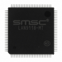
LAN9118-MT SMSC, LAN9118-MT Datasheet - Page 28

LAN9118-MT
Manufacturer Part Number
LAN9118-MT
Description
IC ETHERNET CTRLR 10/100 100TQFP
Manufacturer
SMSC
Type
Single Chip MAC and PHYr
Datasheet
1.LAN9118-MT.pdf
(132 pages)
Specifications of LAN9118-MT
Controller Type
Ethernet Controller
Interface
Serial EEPROM
Voltage - Supply
3.3V
Operating Temperature
0°C ~ 70°C
Mounting Type
Surface Mount
Package / Case
100-TQFP, 100-VQFP
Product
Ethernet Controllers
Number Of Transceivers
1
Standard Supported
IEEE 802.3 or IEEE 802.3u
Data Rate
10 Mbps or 100 Mbps
Supply Voltage (max)
3.3 V
Supply Voltage (min)
0 V
Maximum Operating Temperature
+ 70 C
Ethernet Connection Type
100BASE-TX or 10BASE-T
Minimum Operating Temperature
0 C
Mounting Style
SMD/SMT
Lead Free Status / RoHS Status
Lead free / RoHS Compliant
Current - Supply
-
Lead Free Status / Rohs Status
Lead free / RoHS Compliant
Other names
638-1013
Available stocks
Company
Part Number
Manufacturer
Quantity
Price
Company:
Part Number:
LAN9118-MT
Manufacturer:
SMSC
Quantity:
6
Company:
Part Number:
LAN9118-MT
Manufacturer:
Microchip Technology
Quantity:
10 000
Part Number:
LAN9118-MT
Manufacturer:
SMSC
Quantity:
20 000
Company:
Part Number:
LAN9118-MT-E2
Manufacturer:
INTEL
Quantity:
18
Part Number:
LAN9118-MT-E2
Manufacturer:
SMSC
Quantity:
20 000
Revision 1.5 (07-11-08)
Reserved
FIELD
FIELD
30:0
2:1
31
3
0
Filter 3 Offset
Note 3.3
The Filter i Byte Mask defines which incoming frame bytes Filter i will examine to determine whether
or not this is a wake-up frame.
The Filter i command register controls Filter i operation.
The Filter i Offset register defines the offset in the frame’s destination address field from which the
frames are examined by Filter i.
DESCRIPTION
Must be zero (0)
Byte Mask: If bit j of the byte mask is set, the CRC machine processes byte number pattern - (offset
+ j) of the incoming frame. Otherwise, byte pattern - (offset + j) is ignored.
DESCRIPTION
Address Type: Defines the destination address type of the pattern. When bit is set, the pattern
applies
only to multicast frames. When bit is cleared, the pattern applies only to unicast frames.
RESERVED
Enable Filter: When bit is set, Filter i is enabled, otherwise, Filter i is disabled.
Command
Filter 3
Filter 1 CRC-16
Filter 3 CRC-16
When wake-up frame detection is enabled via the WUEN bit of the
Control and Status
the state of the Disable Broadcast Frames (BCAST) bit in the
Register.
Table 3.2 Wake-Up Frame Filter Register Structure
Reserved
Table 3.3 Filter i Byte Mask Bit Definitions
Table 3.4 Filter i Command Bit Definitions
Filter 2 Offset
FILTER I BYTE MASK DESCRIPTION
Command
Register, a broadcast wake-up frame will wake-up the device despite
Table
FILTER i COMMANDS
Table 3.5
Filter 2
Filter 0 Byte Mask
Filter 1 Byte Mask
Filter 2 Byte Mask
Filter 3 Byte Mask
DATASHEET
3.3, describes the byte mask’s bit fields.
28
describes the Filter i Offset bit fields.
High Performance Single-Chip 10/100 Non-PCI Ethernet Controller
Reserved
Filter 1Offset
Table 3.4
Command
Filter 1
Filter 0 CRC-16
Filter 2 CRC-16
shows the Filter I command register.
Reserved
MAC_CR—MAC Control
Filter 0 Offset
WUCSR—Wake-up
SMSC LAN9118
Command
Filter 0
Datasheet


