EWR1601-0G POWER ONE, EWR1601-0G Datasheet - Page 18
EWR1601-0G
Manufacturer Part Number
EWR1601-0G
Description
DC/DC Converters & Regulators
Manufacturer
POWER ONE
Datasheet
1.LWN1801-6E.pdf
(25 pages)
Specifications of EWR1601-0G
Output Power
120 W
Input Voltage Range
66 V to 150 V
Input Voltage (nominal)
110 V
Number Of Outputs
1
Output Voltage (channel 1)
24.7 V
Output Current (channel 1)
5 A
Package / Case Size
103 mm x 114 mm x 138 mm
Output Type
Regulated
Lead Free Status / Rohs Status
Lead free / RoHS Compliant


Fig. 17a
View of the input terminals (cage clamp style)
BCD20020-G Rev AB1, 17-Nov-09
Safety and Installation Instructions
Terminal Allocation
The terminal allocation tables define the electrical potential
of the converters.
Fig. 17b
View of the output terminals (cage clamp style)
Table 13a: Input terminals of LW models
Table 13b: Input terminals of EW models
Table 13c: Terminal allocation output side
Pin no.
1
2
3
4
5
6
7
8
9
10
11
Pin no.
1
2
3
Pin no.
1
2
3
Pin des.
+
+
–
–
+
+
–
–
AUX
Pin designation
N
L
Pin designation
Vi–
Vi+
1
Single output
Functional
earth to load
Output positive
Output positive
Output negative
Output negative
Output positive
Output positive
Output negative
Output negative
Option
Functional
earth to load
2
®
3
4
1
5
2
Electrical determination
Protective earth PE
Input neutral, DC negative
Input phase, DC positive
Electrical determination
Protective earth PE
Input negative
Input positive
6
10066
3
7
8
9
10067
Double output
Functional
earth to load
Output 1 positive
Output 1 positive
Output 1 negative
Output 1 negative
Output 2 positive
Output 2 positive
Output 2 negative
Output 2 negative
Option
Functional
earth to load
10
11
125, 250 Watt AC-DC and DC-DC DIN-Rail Converters
Page 18 of 25
Installation Instructions
The converters of the W Series are components, intended
exclusively for inclusion within other equipment by professional
installers. Installation must strictly follow the national safety
regulations in compliance with the enclosure, mounting,
creepage, clearance, casualty, markings and segregation
requirements of the end-use application.
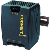
DIN-rail mounting is possible with the built-in snap-fit device
on a DIN-rail. This fulfills the mechanical transport requirements
as per ETSI 300019-1-2, class 2 (vertical).
To fulfill the requirements of IEC 721-3-2, class 2.1 (vertical), 2
additional fixing brackets DMB-EWG [formerly HZZ00624] (see
Accessories) must be fitted on the bottom side of the DIN-rail.
For heavy duty railway applications, we recommend installing
all 4 fixing brackets DMB-EWG.
Wall mounting is possible with the wall-mounting brackets
UMB-W [HZZ00618] (see Accessories). This complies with
IEC 721-3-2, class 2.2 (vertical and horizontal).
The converters of the W Series are class I equipment: Input
terminal 1 ( ) and the output terminals 1 and 11 ( )
are reliably connected to the case. For safety reasons it is
Fig. 18a
Snap-fit mounting to DIN-Rail.
Fig. 18b
Dismounting from DIN-rail. Use proper tool (min. 3 mm
screwdriver) and adequate force.
essential to connect the input terminal 1 ( ) to the protective
earth of the supply system. Output terminals 1 and 11 can be
used to connect the output voltage(s) or the load to functional
earth.
The phase input (L or Vi+) is internally fused; see Input Fuse.
Caution: Install the converters vertically, and make sure that there
is sufficient airflow available for convection cooling. The minimum
space to the next device should be: top/bottom: 30 mm, left/right:
20 mm.
W Series Data Sheet
www.power-one.com
10073
Related parts for EWR1601-0G
Image
Part Number
Description
Manufacturer
Datasheet
Request
R


Part Number:
Description:
SWITCHING POWER SUPPLIES, SINGLE OUTPUT, 80 WATTS
Manufacturer:
POWER ONE
Datasheet:
Part Number:
Description:
HAS SERIES - 30 WATT
Manufacturer:
POWER ONE
Datasheet:
Part Number:
Description:
SINGLE OUTPUT
Manufacturer:
POWER ONE
Datasheet:

Part Number:
Description:
BRS DC/DC converters(1.5 WATT)
Manufacturer:
Power-One
Datasheet:
Part Number:
Description:
3...15 Watt DC-DC Converter
Manufacturer:
Power-One
Datasheet:
Part Number:
Description:
HBS SERIES - 100 WATT
Manufacturer:
Power-One
Datasheet:
Part Number:
Description:
3...15 Watt DC-DC Converter
Manufacturer:
Power-One
Datasheet:
Part Number:
Description:
BUS DC/DC converters(3 WATT)
Manufacturer:
Power-One
Datasheet:
Part Number:
Description:
HES SERIES 150 WATT
Manufacturer:
Power-One
Datasheet:
Part Number:
Description:
1.25 WATT
Manufacturer:
Power-One
Datasheet: