EWR1601-0G POWER ONE, EWR1601-0G Datasheet - Page 13
EWR1601-0G
Manufacturer Part Number
EWR1601-0G
Description
DC/DC Converters & Regulators
Manufacturer
POWER ONE
Datasheet
1.LWN1801-6E.pdf
(25 pages)
Specifications of EWR1601-0G
Output Power
120 W
Input Voltage Range
66 V to 150 V
Input Voltage (nominal)
110 V
Number Of Outputs
1
Output Voltage (channel 1)
24.7 V
Output Current (channel 1)
5 A
Package / Case Size
103 mm x 114 mm x 138 mm
Output Type
Regulated
Lead Free Status / Rohs Status
Lead free / RoHS Compliant


BCD20020-G Rev AB1, 17-Nov-09
Electromagnetic Compatibility (EMC)
Electromagnetic Immunity
The W Series has been successfully tested to the following specifications:
Table 8: Electromagnetic immunity (type tests)
Phenomenon
Electrostatic
discharge
(to case)
Electromagnetic
field RF
Electrical fast
transients/burst
Surges
Conducted
disturbances
Surges
(EW models)
1
2
3
4
5
6
7
8
9
i = input, o = output, c = case.
A = Normal operation, no deviation from specifications, B = Normal operation, temporary loss of function or deviation from specs. possible.
Exceeds EN 50121-3-2:2006 table 9.3 and EN 50121-4:2006 table 1.4.
EW models: 20 V/m, which corresponds to EN 50121-3-2:2006 table 9.1 and exceeds EN 50121-4:2006 table 1.1.
EW models only. Corresponds to EN 50121-3-2:2006 table 9.2 and EN 50121-4:2006 table 1.2 (compliance with digital mobile phones).
EW models are tested to level 3 (±2000 V
Complies with EN 50121-3-2:2006 table 7.3 and EN 50121-4:2006 table 2.3.
Corresponds to EN 50121-3-2:2006 table 8.1 and EN 50121-4:2006 table 3.1 (radio frequency common mode).
Corresponds to EN 50121-3-2:2000. Covers EN 50155:1995, RIA12, direct transients, wafeform D (EW models only).
Standard
IEC/EN
61000-4-2
IEC/EN
61000-4-3
ENV 50204
IEC/EN
61000-4-3
(EW models)
IEC/EN
61000-4-4
IEC /EN
61000-4-5
IEC /EN
61000-4-6
IEC/EN
50155:2001
®
Level
wave
4
3
3
3
A
3
2
4
3
5
3
4
6
7
7
8
9
6
contact discharge
i, o, signal wires
direct coupling
capacitive, o/c
air discharge
p)
Coupling
±i / c, +i /– i
+i/c, –i/c
+i/c, –i/c
antenna
antenna
antenna
mode
, corresponding to EN 50121-3-2:2006 table 7.2 and EN 50121-4:2006 table 2.2.
+i/–i
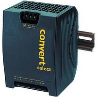
125, 250 Watt AC-DC and DC-DC DIN-Rail Converters
1
(140 dBµV)
±4000 V
Page 13 of 25
±2000 V
±2000 V
15000 V
±1000 V
10 V/m
applied
8000 V
10 VAC
1800 V
10 V/m
20 V/m
10 Vm
5 V/m
Value
p
p
p
4
p
p
p
p
6
200 Hz repet. frequ.
5 kHz over 15 ms,
bursts of 5/50 ns,
burst period: 300
50% duty cycle,
80% AM, 1 kHz
Waveform
1.2/50 µs
1.2/50 µs
AM 80%
AM 80%
1/50 ns
5/50 µs
1 kH z
1 kHz
ms
Source
imped.
330
150
50
12
n.a.
n.a.
n.a.
2
5
5 pos. and 5 neg.
5 pos. and 5 neg.
1400 – 2100 MHz
2100 – 2500 MHz
800 – 1000 MHz
10 positive and
80 – 1000 MHz
W Series Data Sheet
60 s positive +
coupling mode
coupling mode
0.15 – 80 MHz
transients per
60 s negative
900 ±5 MHz
10 negative
procedure
discharges
surges per
pulses
Test
www.power-one.com
oper. form.
yes
yes
yes
yes
yes
yes
yes
yes
In
Per-
A
A
A
A
A
B
A
B
2
Related parts for EWR1601-0G
Image
Part Number
Description
Manufacturer
Datasheet
Request
R


Part Number:
Description:
SWITCHING POWER SUPPLIES, SINGLE OUTPUT, 80 WATTS
Manufacturer:
POWER ONE
Datasheet:
Part Number:
Description:
HAS SERIES - 30 WATT
Manufacturer:
POWER ONE
Datasheet:
Part Number:
Description:
SINGLE OUTPUT
Manufacturer:
POWER ONE
Datasheet:

Part Number:
Description:
BRS DC/DC converters(1.5 WATT)
Manufacturer:
Power-One
Datasheet:
Part Number:
Description:
3...15 Watt DC-DC Converter
Manufacturer:
Power-One
Datasheet:
Part Number:
Description:
HBS SERIES - 100 WATT
Manufacturer:
Power-One
Datasheet:
Part Number:
Description:
3...15 Watt DC-DC Converter
Manufacturer:
Power-One
Datasheet:
Part Number:
Description:
BUS DC/DC converters(3 WATT)
Manufacturer:
Power-One
Datasheet:
Part Number:
Description:
HES SERIES 150 WATT
Manufacturer:
Power-One
Datasheet:
Part Number:
Description:
1.25 WATT
Manufacturer:
Power-One
Datasheet: