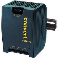
EWR1601-0G POWER ONE, EWR1601-0G Datasheet - Page 11

EWR1601-0G
Manufacturer Part Number
EWR1601-0G
Description
DC/DC Converters & Regulators
Manufacturer
POWER ONE
Datasheet
1.LWN1801-6E.pdf
(25 pages)
Specifications of EWR1601-0G
Output Power
120 W
Input Voltage Range
66 V to 150 V
Input Voltage (nominal)
110 V
Number Of Outputs
1
Output Voltage (channel 1)
24.7 V
Output Current (channel 1)
5 A
Package / Case Size
103 mm x 114 mm x 138 mm
Output Type
Regulated
Lead Free Status / Rohs Status
Lead free / RoHS Compliant
Parallel Operation
Double-output models exhibit an independant
control logic each. Both outputs can be
connected in parallel, provided that the
options S (included in M1) and R are not used,
since they influence only the 2
two power trains share the current due to their
output voltage droop characteristic.
Up to 3 converters with the same output
voltage may be operated in parallel. It is
possible to parallel W Series with X Series
converters.
Reasonable current sharing is achieved by
the droop characteristic. Correct mode of
operation is highly dependent upon the wiring
of the converters and the impedance of these
wires. Use wires with equal length and equal
cross sections of min. 1.5 mm
results for parallel operation can be achieved
with the wiring shown in fig. 6.
Parallel operation of single-output models
using the option R (output voltage adjust) is
possible, but not recommended. Refer to fig.
6; the connections between the pins 8 and 9
(both Vo–) should be as short as possible.
Series Connection
Series connection of several outputs up to 150
V is possible. Exceeding an output voltage of
60 V, the output is not SELV.
Output Characteristic and Protection
The output characteristic, individual for each
powertrain, is rectangular with a droop to ease
parallel operation; see fig. 7.
However, a 50% higher output current is
possible for a short time, such allowing start-
up of loads or charging of capacitors; see fig.
8.
Each output is independently protected against internal
overvoltage by means of a second control loop. When the
output voltage exceeds V
Overtemperature Protection
A built-in temperature sensor protects each powertrain is
independently protected against overtemperature. When a
BCD20020-G Rev AB1, 17-Nov-09
Note: Parallel operation is not possible, if a
temperature sensor is connected, as the
sensor eliminates the output voltage droop.
Note: For ORing diodes, we recommend to
use Schottkydiodes, mounted on a commun
heatsink to avoid thermal run away (or the use
of double diodes).
®
o L
, the respective output is disabled.
nd
2
output. The
. The best
125, 250 Watt AC-DC and DC-DC DIN-Rail Converters
Fig. 6
Wiring for single-output converters connected in parallel. Additional wiring
for higher output currents and with the use of option R is shown.
i
i
i
Page 11 of 25
AUX 10
AUX 10
AUX 10
1.0
0.8
0.6
0.4
Vo+ 7
Vo+ 6
Vo+ 3
Vo+ 2
Vo+ 6
0.2
Vo+ 7
Vo+ 3
Vo+ 2
Vo+ 7
Vo+ 6
Vo+ 3
Vo+ 2
Vo- 8
Vo- 4
Vo- 9
Vo- 5
Vo- 9
Vo- 8
Vo- 5
Vo- 4
Vo- 9
Vo- 8
Vo- 5
Vo- 4
o
0
11054b
/
Fig. 7
V
0
o nom
o
versus I
0.2
o
(single-output model, typical values).
0.4
Additional wiring for output currents
Additional wiring, if using the R-input
0.6
W Series Data Sheet
R
0.8
www.power-one.com
1.0
05181a
+
_
o
1.2
Load
10 A
o
/
o nom


