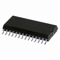
SJA1000T/N1,118 NXP Semiconductors, SJA1000T/N1,118 Datasheet - Page 32

SJA1000T/N1,118
Manufacturer Part Number
SJA1000T/N1,118
Description
IC STAND-ALONE CAN CTRLR 28-SOIC
Manufacturer
NXP Semiconductors
Datasheet
1.SJA1000TN1112.pdf
(68 pages)
Specifications of SJA1000T/N1,118
Package / Case
28-SOIC (7.5mm Width)
Controller Type
CAN Interface
Interface
CAN
Voltage - Supply
4.5 V ~ 5.5 V
Current - Supply
15mA
Operating Temperature
-40°C ~ 125°C
Mounting Type
Surface Mount
Product
Controller Area Network (CAN)
Number Of Transceivers
1
Data Rate
1 Mbps
Frequency
24 MHz
Supply Voltage (max)
5.5 V
Supply Voltage (min)
4.5 V
Supply Current (max)
15 mA
Maximum Operating Temperature
+ 125 C
Minimum Operating Temperature
- 40 C
Mounting Style
SMD/SMT
Package
28SO
Maximum Data Rate
1 Mbps
Minimum Single Supply Voltage
4.5 V
Standard Supported
CAN 2.0B
Power Down Mode
Sleep
Maximum Single Supply Voltage
5.5 V
Lead Free Status / RoHS Status
Lead free / RoHS Compliant
Lead Free Status / RoHS Status
Lead free / RoHS Compliant, Lead free / RoHS Compliant
Other names
568-1123-2
935230920118
SJA1000TD-T
935230920118
SJA1000TD-T
Available stocks
Company
Part Number
Manufacturer
Quantity
Price
Company:
Part Number:
SJA1000T/N1,118
Manufacturer:
XILINX
Quantity:
125
Part Number:
SJA1000T/N1,118
Manufacturer:
NXP/恩智浦
Quantity:
20 000
Philips Semiconductors
Notes
1. A wake-up interrupt is also generated, if the CPU tries to set the sleep bit while the CAN controller is involved in bus
2. The behaviour of this bit is equivalent to that of the receive buffer status bit with the exception, that RI depends on
6.4.7
The register allows to enable different types of interrupt sources which are indicated to the CPU.
The interrupt enable register appears to the CPU as a read/write memory.
Table 16 Bit interpretation of the interrupt enable register (IER); CAN address 4
2000 Jan 04
IER.7
IER.6
IER.5
IER.4
IER.3
IER.2
IER.1
IER.0
Stand-alone CAN controller
activities or a CAN interrupt is pending.
the corresponding interrupt enable bit (RIE). So the receive interrupt bit is not cleared upon a read access to the
interrupt register. Giving the command ‘release receive buffer’ will clear RI temporarily. If there is another message
available within the FIFO after the release command, RI is set again. Otherwise RI remains cleared.
BIT
I
NTERRUPT
BEIE
ALIE
EPIE
WUIE
DOIE
EIE
TIE
RIE
SYMBOL
E
NABLE
Bus Error Interrupt
Enable
Arbitration Lost Interrupt
Enable
Error Passive Interrupt
Enable
Wake-Up Interrupt
Enable
Data Overrun Interrupt
Enable
Error Warning Interrupt
Enable
Transmit Interrupt Enable
Receive Interrupt
Enable; note 1
R
EGISTER
NAME
(IER)
VALUE
32
1
0
1
0
1
0
1
0
1
0
1
0
1
0
1
0
enabled; if an bus error has been detected, the
CAN controller requests the respective interrupt
disabled
enabled; if the CAN controller has lost arbitration,
the respective interrupt is requested
disabled
enabled; if the error status of the CAN controller
changes from error active to error passive or vice
versa, the respective interrupt is requested
disabled
enabled; if the sleeping CAN controller wakes up,
the respective interrupt is requested
disabled
enabled; if the data overrun status bit is set (see
status register; Table 14), the CAN controller
requests the respective interrupt
disabled
enabled; if the error or bus status change (see
status register; Table 14), the CAN controller
requests the respective interrupt
disabled
enabled; when a message has been successfully
transmitted or the transmit buffer is accessible
again (e.g. after an abort transmission command),
the CAN controller requests the respective
interrupt
disabled
enabled; when the receive buffer status is ‘full’ the
CAN controller requests the respective interrupt
disabled
FUNCTION
Product specification
SJA1000


