SJA1000T/N1,118 NXP Semiconductors, SJA1000T/N1,118 Datasheet - Page 30
SJA1000T/N1,118
Manufacturer Part Number
SJA1000T/N1,118
Description
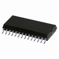
IC STAND-ALONE CAN CTRLR 28-SOIC
Manufacturer
NXP Semiconductors
Datasheet
1.SJA1000TN1112.pdf
(68 pages)
Specifications of SJA1000T/N1,118
Package / Case
28-SOIC (7.5mm Width)
Controller Type
CAN Interface
Interface
CAN
Voltage - Supply
4.5 V ~ 5.5 V
Current - Supply
15mA
Operating Temperature
-40°C ~ 125°C
Mounting Type
Surface Mount
Product
Controller Area Network (CAN)
Number Of Transceivers
1
Data Rate
1 Mbps
Frequency
24 MHz
Supply Voltage (max)
5.5 V
Supply Voltage (min)
4.5 V
Supply Current (max)
15 mA
Maximum Operating Temperature
+ 125 C
Minimum Operating Temperature
- 40 C
Mounting Style
SMD/SMT
Package
28SO
Maximum Data Rate
1 Mbps
Minimum Single Supply Voltage
4.5 V
Standard Supported
CAN 2.0B
Power Down Mode
Sleep
Maximum Single Supply Voltage
5.5 V
Lead Free Status / RoHS Status
Lead free / RoHS Compliant
Lead Free Status / RoHS Status
Lead free / RoHS Compliant, Lead free / RoHS Compliant
Other names
568-1123-2
935230920118
SJA1000TD-T
935230920118
SJA1000TD-T
Available stocks
Company
Part Number
Manufacturer
Quantity
Price
Company:

Part Number:
SJA1000T/N1,118
Manufacturer:
XILINX
Quantity:
125
Part Number:
SJA1000T/N1,118
Manufacturer:
NXP/恩智浦
Quantity:
20 000


Philips Semiconductors
Notes
1. When the transmit error counter exceeds the limit of 255, the bus status bit is set to logic 1 (bus-off), the
2. Errors detected during reception or transmission will effect the error counters according to the CAN 2.0B protocol
3. If both the receive status and the transmit status bits are logic 0 (idle) the CAN-bus is idle. If both bits are set the
4. The transmission complete status bit is set to logic 0 (incomplete) whenever the transmission request bit or the self
5. If the CPU tries to write to the transmit buffer when the transmit buffer status bit is logic 0 (locked), the written byte
6. When a message that is to be received has passed the acceptance filter successfully, the CAN controller needs
7. After reading all messages within the RXFIFO and releasing their memory space with the command release receive
2000 Jan 04
SR.1
SR.0
Stand-alone CAN controller
CAN controller will set the reset mode bit to logic 1 (present) and an error warning interrupt is generated, if enabled.
The transmit error counter is set to 127 and the receive error counter is cleared. It will stay in this mode until the CPU
clears the reset mode bit. Once this is completed the CAN controller will wait the minimum protocol-defined time
(128 occurrences of the bus-free signal) counting down the transmit error counter. After that the bus status bit is
cleared (bus-on), the error status bit is set to logic 0 (ok), the error counters are reset and an error warning interrupt
is generated, if enabled. Reading the TX error counter during this time gives information about the status of the
bus-off recovery.
specification. The error status bit is set when at least one of the error counters has reached or exceeded the CPU
warning limit (EWLR). An error warning interrupt is generated, if enabled. The default value of EWLR after hardware
reset is 96.
controller is waiting to become idle again. After a hardware reset 11 consecutive recessive bits have to be detected
until the idle status is reached. After bus-off this will take 128 of 11 consecutive recessive bits.
reception request bit is set to logic 1. The transmission complete status bit will remain at logic 0 until a message is
transmitted successfully.
will not be accepted and will be lost without this being indicated.
space in the RXFIFO to store the message descriptor and for each data byte which has been received. If there is not
enough space to store the message, that message is dropped and the data overrun condition is indicated to the CPU
at the moment this message becomes valid. If this message is not completed successfully (e.g. due to an error), no
overrun condition is indicated.
buffer this bit is cleared.
BIT
DOS
RBS
SYMBOL
Data Overrun Status;
note 6
Receive Buffer Status;
note 7
NAME
VALUE
30
1
0
1
0
overrun; a message was lost because there was
not enough space for that message in the RXFIFO
absent; no data overrun has occurred since the
last clear data overrun command was given
full; one or more complete messages are available
in the RXFIFO
empty; no message is available
FUNCTION
Product specification
SJA1000
Related parts for SJA1000T/N1,118
Image
Part Number
Description
Manufacturer
Datasheet
Request
R

Part Number:
Description:
IC STAND-ALONE CAN CTRLR 28-SOIC
Manufacturer:
NXP Semiconductors
Datasheet:

Part Number:
Description:
Manufacturer:
NXP Semiconductors
Datasheet:
Part Number:
Description:
IC STAND-ALONE CAN CTRLR 28-SOIC
Manufacturer:
NXP Semiconductors
Datasheet:
Part Number:
Description:
IC STAND-ALONE CAN CTRLR 28-SOIC
Manufacturer:
NXP Semiconductors
Datasheet:
Part Number:
Description:
Manufacturer:
NXP Semiconductors
Datasheet:
Part Number:
Description:
Manufacturer:
NXP Semiconductors
Datasheet:
Part Number:
Description:
Manufacturer:
NXP Semiconductors
Datasheet:

Part Number:
Description:
CONTROLLER, CAN, STANDALONE, 28SOIC
Manufacturer:
NXP Semiconductors
Datasheet:
Part Number:
Description:
Stand-alone Can Controller
Manufacturer:
NXP Semiconductors
Datasheet:
Part Number:
Description:
Network Controller & Processor ICs STAND ALONE CAN CONTROLLER
Manufacturer:
NXP Semiconductors
Datasheet:
Part Number:
Description:
NXP Semiconductors designed the LPC2420/2460 microcontroller around a 16-bit/32-bitARM7TDMI-S CPU core with real-time debug interfaces that include both JTAG andembedded trace
Manufacturer:
NXP Semiconductors
Datasheet:

Part Number:
Description:
NXP Semiconductors designed the LPC2458 microcontroller around a 16-bit/32-bitARM7TDMI-S CPU core with real-time debug interfaces that include both JTAG andembedded trace
Manufacturer:
NXP Semiconductors
Datasheet:
Part Number:
Description:
NXP Semiconductors designed the LPC2468 microcontroller around a 16-bit/32-bitARM7TDMI-S CPU core with real-time debug interfaces that include both JTAG andembedded trace
Manufacturer:
NXP Semiconductors
Datasheet:
Part Number:
Description:
NXP Semiconductors designed the LPC2470 microcontroller, powered by theARM7TDMI-S core, to be a highly integrated microcontroller for a wide range ofapplications that require advanced communications and high quality graphic displays
Manufacturer:
NXP Semiconductors
Datasheet:
Part Number:
Description:
NXP Semiconductors designed the LPC2478 microcontroller, powered by theARM7TDMI-S core, to be a highly integrated microcontroller for a wide range ofapplications that require advanced communications and high quality graphic displays
Manufacturer:
NXP Semiconductors
Datasheet: