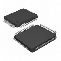
KSZ8873MLL Micrel Inc, KSZ8873MLL Datasheet - Page 9

KSZ8873MLL
Manufacturer Part Number
KSZ8873MLL
Description
IC ETHERNET SWITCH 3PORT 64-LQFP
Manufacturer
Micrel Inc
Specifications of KSZ8873MLL
Data Rate
100Mbps
Controller Type
Ethernet Switch Controller
Interface
MII
Voltage - Supply
1.8V, 2.5V, 3.3V
Operating Temperature
0°C ~ 70°C
Mounting Type
Surface Mount
Package / Case
64-LQFP
No. Of Ports
3
Ethernet Type
IEEE 802.3u
Supply Current
115mA
Supply Voltage Range
2.5V, 3.3V
Digital Ic Case Style
LQFP
No. Of Pins
64
Svhc
No SVHC (15-Dec-2010)
Base
RoHS Compliant
Number Of Primary Switch Ports
3
Internal Memory Buffer Size
32
Fiber Support
No
Integrated Led Drivers
Yes
Phy/transceiver Interface
MII
Power Supply Type
Analog/Digital
Data Rate (typ)
10/100Mbps
Vlan Support
Yes
Operating Temperature (max)
70C
Operating Temperature (min)
0C
Mounting
Surface Mount
Jtag Support
No
Operating Supply Voltage (max)
1.89/3.465V
Operating Temperature Classification
Commercial
Interface Type
MII, RMII
Operating Temperature Range
0°C To +70°C
Rohs Compliant
Yes
Lead Free Status / RoHS Status
Lead free / RoHS Compliant
Current - Supply
-
Lead Free Status / RoHS Status
Compliant, Lead free / RoHS Compliant
Other names
576-3459
Available stocks
Company
Part Number
Manufacturer
Quantity
Price
Company:
Part Number:
KSZ8873MLL
Manufacturer:
Micrel Inc
Quantity:
1 934
Company:
Part Number:
KSZ8873MLL
Manufacturer:
ADI
Quantity:
27
Company:
Part Number:
KSZ8873MLL AM
Manufacturer:
Micrel
Quantity:
1 638
Company:
Part Number:
KSZ8873MLLJ
Manufacturer:
Micrel
Quantity:
323
Micrel, Inc.
KSZ8873MLL/FLL/RLL
List of Figures
Figure 1. Typical Straight Cable Connection ....................................................................................................................... 19
Figure 2. Typical Crossover Cable Connection ................................................................................................................... 20
Figure 3. Auto-Negotiation and Parallel Operation .............................................................................................................. 21
Figure 4. Destination Address Lookup Flow Chart, Stage 1................................................................................................ 25
Figure 5. Destination Address Resolution Flow Chart, Stage 2........................................................................................... 26
Figure 6. 802.1p Priority Field Format ................................................................................................................................. 33
Figure 7. Tail Tag Frame Format ......................................................................................................................................... 35
Figure 8. Tail Tag Rules....................................................................................................................................................... 36
Figure 9. EEPROM Configuration Timing Diagram ............................................................................................................. 38
Figure 10. SPI Write Data Cycle .......................................................................................................................................... 40
Figure 11. SPI Read Data Cycle .......................................................................................................................................... 40
Figure 12. SPI Multiple Write ............................................................................................................................................... 40
Figure 13. SPI Multiple Read ............................................................................................................................................... 41
Figure 14. Far-End Loopback Path ...................................................................................................................................... 42
Figure 15. Near-end (Remote) Loopback Path.................................................................................................................... 43
Figure 16. EEPROM Interface Input Timing Diagram.......................................................................................................... 90
Figure 17. EEPROM Interface Output Timing Diagram ....................................................................................................... 90
Figure 18. MAC Mode MII Timing – Data Received from MII .............................................................................................. 91
Figure 19. MAC Mode MII Timing – Data Transmitted to MII ............................................................................................. 91
Figure 20. PHY Mode MII Timing – Data Received from MII............................................................................................... 92
Figure 21. PHY Mode MII Timing – Data Transmitted to MII............................................................................................... 92
Figure 22. RMII Timing – Data Received from RMII ............................................................................................................ 93
Figure 23. RMII Timing – Data Transmitted to RMII ............................................................................................................ 93
Figure 24. I2C Input Timing.................................................................................................................................................. 94
Figure 25. I2C Start Bit Timing............................................................................................................................................. 94
Figure 26. I2C Stop Bit Timing ............................................................................................................................................. 94
Figure 27. I2C Output Timing............................................................................................................................................... 94
Figure 28. SPI Input Timing ................................................................................................................................................. 96
Figure 29. SPI Output Timing............................................................................................................................................... 97
Figure 30. Auto-Negotiation Timing ..................................................................................................................................... 98
Figure 31. MDC/MDIO Timing.............................................................................................................................................. 99
Figure 35. 64-Pin LQFP Package ...................................................................................................................................... 104
September 2010
9
M9999-092309-1.2


