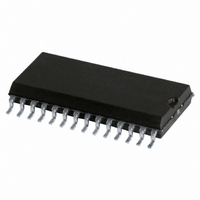
SJA1000T/N1,112 NXP Semiconductors, SJA1000T/N1,112 Datasheet - Page 26

SJA1000T/N1,112
Manufacturer Part Number
SJA1000T/N1,112
Description
IC STAND-ALONE CAN CTRLR 28-SOIC
Manufacturer
NXP Semiconductors
Datasheet
1.SJA1000TN1112.pdf
(68 pages)
Specifications of SJA1000T/N1,112
Package / Case
28-SOIC (7.5mm Width)
Controller Type
CAN Interface
Interface
CAN
Voltage - Supply
4.5 V ~ 5.5 V
Current - Supply
15mA
Operating Temperature
-40°C ~ 125°C
Mounting Type
Surface Mount
Product
Controller Area Network (CAN)
Number Of Transceivers
1
Data Rate
1 Mbps
Supply Voltage (max)
5.5 V
Supply Voltage (min)
4.5 V
Supply Current (max)
15 mA
Maximum Operating Temperature
+ 125 C
Minimum Operating Temperature
- 40 C
Mounting Style
SMD/SMT
Lead Free Status / RoHS Status
Lead free / RoHS Compliant
Lead Free Status / RoHS Status
Lead free / RoHS Compliant, Lead free / RoHS Compliant
Other names
568-3994-5
935230920112
SJA1000TD
SJA1000TD
935230920112
SJA1000TD
SJA1000TD
Philips Semiconductors
Notes
1. X means that the value of these registers or bits is not influenced.
2. Remarks in brackets explain functional meaning.
3. On bus-off the error warning interrupt is set, if enabled.
4. If the reset mode was entered due to a bus-off condition, the receive error counter is cleared and the transmit error
5. Internal read/write pointers of the RXFIFO are reset to their initial values. A subsequent read access to the RXB
6.4.3
The contents of the mode register are used to change the behaviour of the CAN controller. Bits may be set or reset by
the CPU which uses the control register as a read/write memory. Reserved bits are read as logic 0.
Table 12 Bit interpretation of the mode register (MOD); CAN address ‘0’
2000 Jan 04
MOD.7
MOD.6
MOD.5
MOD.4
MOD.3
MOD.2
Stand-alone CAN controller
counter is initialized to 127 to count-down the CAN-defined bus-off recovery time consisting of 128 occurrences of
11 consecutive recessive bits.
would show undefined data values (parts of old messages).
If a message is transmitted, this message is written in parallel to the receive buffer. A receive interrupt is generated
only if this transmission was forced by the self reception request. So, even if the receive buffer is empty, the last
transmitted message may be read from the receive buffer until it is overwritten by the next received or transmitted
message.
Upon a hardware reset, the RXFIFO pointers are reset to the physical RAM address ‘0’. Setting CR.0 by software or
due to the bus-off event will reset the RXFIFO pointers to the currently valid FIFO start address (RBSA register)
which is different from the RAM address ‘0’ after the first release receive buffer command.
BIT
M
ODE
SM
AFM
STM
SYMBOL
R
EGISTER
Sleep Mode; note 1
Acceptance Filter Mode;
note 2
Self Test Mode; note 2
(MOD)
NAME
VALUE
26
1
0
1
0
1
0
reserved
reserved
reserved
sleep; the CAN controller enters sleep mode if no
CAN interrupt is pending and if there is no bus
activity
wake-up; the CAN controller wakes up if sleeping
single; the single acceptance filter option is
enabled (one filter with the length of 32 bit is
active)
dual; the dual acceptance filter option is enabled
(two filters, each with the length of 16 bit are
active)
self test; in this mode a full node test is possible
without any other active node on the bus using the
self reception request command; the
CAN controller will perform a successful
transmission, even if there is no acknowledge
received
normal; an acknowledge is required for successful
transmission
FUNCTION
Product specification
SJA1000


