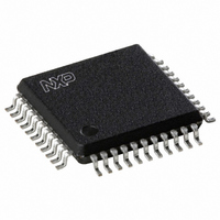
UDA1384H/N1,557 NXP Semiconductors, UDA1384H/N1,557 Datasheet - Page 8

UDA1384H/N1,557
Manufacturer Part Number
UDA1384H/N1,557
Description
IC AUDIO CODEC 44-QFP
Manufacturer
NXP Semiconductors
Type
Audio Codecr
Datasheet
1.UDA1384HN1557.pdf
(55 pages)
Specifications of UDA1384H/N1,557
Data Interface
I²C, Serial
Resolution (bits)
24 b
Number Of Adcs / Dacs
5 / 6
Sigma Delta
No
S/n Ratio, Adcs / Dacs (db) Typ
98 / 110 (Differential), 98 / 110 (Single-Ended)
Voltage - Supply, Analog
2.7 V ~ 3.6 V
Voltage - Supply, Digital
2.7 V ~ 3.6 V
Operating Temperature
-20°C ~ 85°C
Mounting Type
Surface Mount
Package / Case
44-MQFP, 44-PQFP
Lead Free Status / RoHS Status
Lead free / RoHS Compliant
Other names
568-3450
935274756557
UDA1384H
935274756557
UDA1384H
Available stocks
Company
Part Number
Manufacturer
Quantity
Price
Company:
Part Number:
UDA1384H/N1,557
Manufacturer:
NXP Semiconductors
Quantity:
10 000
Philips Semiconductors
9397 750 14366
Product data sheet
8.2 Audio analog-to-digital converter (audio ADC)
8.3 Voice Analog-to-Digital Converter (voice ADC)
8.4 Decimation filter of audio ADC
8.5 Decimation filter of voice ADC
The audio analog-to-digital front-end of the UDA1384 consists of 4-channel single-ended
ADCs with programmable gain stage (from 0 dB to 24 dB with 3 dB steps), controlled via
the microcontroller interface. Using the PGA feature, it is possible to accept an input signal
of 900 mV (RMS) or 1.8 V (RMS) if an external resistor of 10 k is used in series. The
schematic of audio ADC front-end is shown in
The voice analog-to-digital front-end of the UDA1384 consists of a single-channel
single-ended ADC with a fixed gain (26 dB) Low Noise Amplifier (LNA). Together with the
digital variable gain amplification stage, the voice ADC provides optimal processing and
reproduction of the microphone signal. The supported sampling frequency range is from
7 kHz to 50 kHz. Power-down of the LNA and the ADC can be controlled separately.
The decimation from 64f
characteristics with a decimation factor of 8. The second stage consists of three half-band
filters, each decimating by a factor of 2. The filter characteristics are shown in
Table 7:
The voice ADC decimation filter is realized with the combination of a Finite Impulse
Response (FIR) filter and Infinite Impulse Response (IIR) filter for shorter group delay. The
filter characteristics are shown in
the ADC is hard muted for a certain period. This hard-mute time can be chosen between
1024 samples and 2048 samples.
Item
Pass-band ripple
Pass-band droop
Stop band
Dynamic range
Fig 3. Schematic of audio ADC front-end
Decimation filter characteristics (audio ADC)
input signal
Rev. 02 — 17 January 2005
2 V (RMS)
s
is performed in two stages. The first stage realizes
Condition
0f
0.45f
> 0.55f
0f
s
s
10 k
to 0.45f
to 0.45f
Table
s
s
VINL,
VINR
8. During the power-on sequence, the output of
s
s
10 k
V
Figure
ref
10 k (0 dB setting)
Multichannel audio coder-decoder
3.
V
mgu582
DDA
= 3.3 V
© Koninklijke Philips Electronics N.V. 2005. All rights reserved.
Value (dB)
> 135
0.01
0.2
70
ADC
UDA1384
Table
----------
sin
x
x
4
8 of 55
7.


