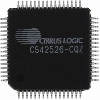
CS42526-CQZ Cirrus Logic Inc, CS42526-CQZ Datasheet - Page 67

CS42526-CQZ
Manufacturer Part Number
CS42526-CQZ
Description
IC CODEC S/PDIF RCVR 64LQFP
Manufacturer
Cirrus Logic Inc
Type
General Purposer
Specifications of CS42526-CQZ
Package / Case
64-LQFP
Data Interface
Serial
Resolution (bits)
24 b
Number Of Adcs / Dacs
2 / 6
Sigma Delta
Yes
Dynamic Range, Adcs / Dacs (db) Typ
114 / 114
Voltage - Supply, Analog
4.75 V ~ 5.25 V
Voltage - Supply, Digital
3.13 V ~ 5.25 V
Operating Temperature
-10°C ~ 70°C
Mounting Type
Surface Mount
Number Of Adc Inputs
2
Number Of Dac Outputs
6
Conversion Rate
192 KSPS
Interface Type
Serial (SPI)
Resolution
24 bit
Operating Supply Voltage
3.3 V, 5 V
Maximum Operating Temperature
+ 70 C
Mounting Style
SMD/SMT
Minimum Operating Temperature
- 10 C
Number Of Channels
2 ADC/6 DAC
Thd Plus Noise
- 100 dB ADC / - 100 dB DAC
Lead Free Status / RoHS Status
Lead free / RoHS Compliant
Lead Free Status / RoHS Status
Lead free / RoHS Compliant, Lead free / RoHS Compliant
Other names
598-1037
Available stocks
Company
Part Number
Manufacturer
Quantity
Price
Company:
Part Number:
CS42526-CQZ
Manufacturer:
ADI
Quantity:
426
Company:
Part Number:
CS42526-CQZ
Manufacturer:
CRYSTAL
Quantity:
850
Company:
Part Number:
CS42526-CQZ
Manufacturer:
Cirrus Logic Inc
Quantity:
10 000
Company:
Part Number:
CS42526-CQZR
Manufacturer:
Cirrus Logic Inc
Quantity:
10 000
DS585F1
6.23.3 C-DATA BUFFER CONTROL (CAM)
6.23.4 CHANNEL SELECT (CHS)
6.24
The bits in this register can be associated with either channel A or B of the received data. The desired channel is
selected with the CHS bit of the Channel Status Data Buffer Control register.
6.24.1 AUXILIARY DATA WIDTH (AUXX)
AUX3
7
Receiver Channel Status (address 25h) (Read Only)
Default = 0
0 - One byte mode
1 - Two byte mode
Function:
Sets the C-data buffer control port access mode.
Default = 0
Function:
When set to ‘0’, channel A information is displayed in the receiver channel status register. Channel A
information is output during control port reads when CAM is set to ‘0’ (one byte mode).
When set to ‘1’, channel B information is displayed in the receiver channel status register. Channel B
information is output during control port reads when CAM is set to ‘0’ (one byte mode).
Default = xxxx
Function:
Displays the incoming auxiliary data field width, as indicated by the incoming channel status bits, de-
coded according to IEC60958.
AUX2
AUX3
6
0
0
0
0
0
0
0
0
1
1
AUX2
0
0
0
0
1
1
1
1
0
0
AUX1
5
Table 20. Auxiliary Data Width Selection
AUX1
0
0
1
1
0
0
1
1
0
0
AUX0
4
AUX0
0
1
0
1
0
1
0
1
0
1
Auxiliary data is not present
PRO
Auxiliary data is 1 bit long
Auxiliary data is 2 bit long
Auxiliary data is 3 bit long
Auxiliary data is 4 bit long
Auxiliary data is 5 bit long
Auxiliary data is 6 bit long
Auxiliary data is 7 bit long
Auxiliary data is 8 bit long
1001 - 1111 is Reserved
3
Description
AUDIO
2
COPY
1
CS42526
ORIG
0
67


