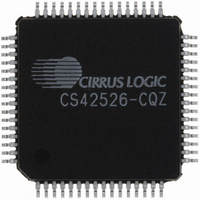
CS42526-CQZ Cirrus Logic Inc, CS42526-CQZ Datasheet - Page 41

CS42526-CQZ
Manufacturer Part Number
CS42526-CQZ
Description
IC CODEC S/PDIF RCVR 64LQFP
Manufacturer
Cirrus Logic Inc
Type
General Purposer
Specifications of CS42526-CQZ
Package / Case
64-LQFP
Data Interface
Serial
Resolution (bits)
24 b
Number Of Adcs / Dacs
2 / 6
Sigma Delta
Yes
Dynamic Range, Adcs / Dacs (db) Typ
114 / 114
Voltage - Supply, Analog
4.75 V ~ 5.25 V
Voltage - Supply, Digital
3.13 V ~ 5.25 V
Operating Temperature
-10°C ~ 70°C
Mounting Type
Surface Mount
Number Of Adc Inputs
2
Number Of Dac Outputs
6
Conversion Rate
192 KSPS
Interface Type
Serial (SPI)
Resolution
24 bit
Operating Supply Voltage
3.3 V, 5 V
Maximum Operating Temperature
+ 70 C
Mounting Style
SMD/SMT
Minimum Operating Temperature
- 10 C
Number Of Channels
2 ADC/6 DAC
Thd Plus Noise
- 100 dB ADC / - 100 dB DAC
Lead Free Status / RoHS Status
Lead free / RoHS Compliant
Lead Free Status / RoHS Status
Lead free / RoHS Compliant, Lead free / RoHS Compliant
Other names
598-1037
Available stocks
Company
Part Number
Manufacturer
Quantity
Price
Company:
Part Number:
CS42526-CQZ
Manufacturer:
ADI
Quantity:
426
Company:
Part Number:
CS42526-CQZ
Manufacturer:
CRYSTAL
Quantity:
850
Company:
Part Number:
CS42526-CQZ
Manufacturer:
Cirrus Logic Inc
Quantity:
10 000
Company:
Part Number:
CS42526-CQZR
Manufacturer:
Cirrus Logic Inc
Quantity:
10 000
CS42526
4.10
Power Supply, Grounding, and PCB Layout
As with any high-resolution converter, the CS42526 requires careful attention to power supply and ground-
ing arrangements if its potential performance is to be realized. Figure
5
shows the recommended power ar-
rangements, with VA and VARX connected to clean supplies. VD, which powers the digital circuitry, may be
run from the system logic supply. Alternatively, VD may be powered from the analog supply via a ferrite
bead. In this case, no additional devices should be powered from VD.
For applications where the output of the PLL is required to be low jitter, use a separate, low-noise analog
+5 V supply for VARX, decoupled to AGND. In addition, a separate region of analog ground plane around
the FILT+, VQ, LPFLT, REFGND, AGND, VA, VARX, RXP/and RXP0 pins is recommended.
Extensive use of power and ground planes, ground plane fill in unused areas and surface mount decoupling
capacitors are recommended. Decoupling capacitors should be as near to the pins of the CS42526 as pos-
sible. The low value ceramic capacitor should be the nearest to the pin and should be mounted on the same
side of the board as the CS42526 to minimize inductance effects. All signals, especially clocks, should be
kept away from the FILT+, VQ and LPFLT pins in order to avoid unwanted coupling into the modulators and
PLL. The FILT+ and VQ decoupling capacitors, particularly the 0.1 µF, must be positioned to minimize the
electrical path from FILT+ and REFGND. The CDB42528 evaluation board demonstrates the optimum lay-
out and power supply arrangements.
DS585F1
41


