XPC8240LZU200E Freescale Semiconductor, XPC8240LZU200E Datasheet - Page 37
XPC8240LZU200E
Manufacturer Part Number
XPC8240LZU200E
Description
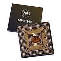
MCU HOST PROCESSOR 352-TBGA
Manufacturer
Freescale Semiconductor
Series
PowerQUICC IIr
Specifications of XPC8240LZU200E
Processor Type
MPC82xx PowerQUICC II 32-bit
Speed
200MHz
Voltage
2.5V
Mounting Type
Surface Mount
Package / Case
352-TBGA
Core Size
32 Bit
Program Memory Size
32KB
Cpu Speed
200MHz
Embedded Interface Type
I2C
Digital Ic Case Style
TBGA
No. Of Pins
352
Supply Voltage Range
2.5V To 2.75V
Rohs Compliant
No
Lead Free Status / RoHS Status
Contains lead / RoHS non-compliant
Features
-
Available stocks
Company
Part Number
Manufacturer
Quantity
Price
Company:

Part Number:
XPC8240LZU200E
Manufacturer:
MOTOLOLA
Quantity:
319
Company:
Part Number:
XPC8240LZU200E
Manufacturer:
Freescale Semiconductor
Quantity:
10 000
Part Number:
XPC8240LZU200E
Manufacturer:
FREESCALE
Quantity:
20 000


The SDRAM_SYNC_OUT signal is intended to be routed halfway out to the SDRAM devices and then
returned to the SDRAM_SYNC_IN input of the MPC8240. The trace length may be used to skew or adjust
the timing window as needed. See the Motorola application note AN1794, “Backside L2 Timing Analysis
for PCB Design Engineers,” for more information on this topic.
1.7.5
The data bus input receivers are normally turned off when no read operation is in progress; therefore, they
do not require pull-up resistors on the bus. The data bus signals are: DH[0:31], DL[0:31], and PAR[0:7].
If the 32-bit data bus mode is selected, the input receivers of the unused data and parity bits (DL[0:31] and
PAR[4:7]) will be disabled, and their outputs will drive logic zeros when they would otherwise normally be
driven. For this mode, these pins do not require pull-up resistors and should be left unconnected by the
system to minimize possible output switching.
The TEST0 pins require pull-up resistors of 120 Ω or less connected to OV
It is recommended that TEST2 have a weak pull-up resistor (2–10 kΩ) connected to GV
It is recommended that the following signals be pulled up to OV
SDA, SCL, SMI, SRESET, TBEN, CHKSTOP_IN, and TEST1.
It is recommended that the following PCI control signals be pulled up to LV
(2–10 kΩ): DEVSEL, FRAME, IRDY, LOCK, PERR, SERR, STOP, TRDY, and INTA. The resistor values
may need to be adjusted stronger to reduce induced noise on specific board designs.
The following pins have internal pull-up resistors enabled at all times: REQ[0:3], REQ4/DA4, TCK, TDI,
TMS, and TRST. See Table 17 for more information.
The following pins have internal pull-up resistors enabled only while the MPC8240 is in the reset state:
GNT4/DA5, DL0, FOE, RCS0, SDRAS, SDCAS, CKE, AS, MCP, MAA[0:2], PMAA[0:2], and
QACK/DA0. See Table 17 for more information.
The following pins are reset configuration pins: GNT4/DA5, DL0, FOE, RCS0, CKE, AS, MCP,
QACK/DA0, MAA[0:2], PMAA[0:2], and PLL_CFG[0:4]/DA[10:6]. These pins are sampled during reset
to configure the device.
Reset configuration pins should be tied to GND via 1-kΩ pull-down resistors to ensure a logic 0 level is read
into the configuration bits during reset if the default logic 1 level is not desired.
Any other unused active-low input pins should be tied to a logic one level through weak pull-up resistors
(2–10 kΩ) to the appropriate power supply. Unused active-high input pins should be tied to GND through
weak pull-down resistors (2–10 kΩ).
1.7.6
Boundary scan testing is enabled through the JTAG interface signals. The TRST signal is optional in the
IEEE 1149.1 specification but is provided on all processors that implement the PowerPC architecture. While
it is possible to force the TAP controller to the reset state using only the TCK and TMS signals, more reliable
power-on reset performance will be obtained if the TRST signal is asserted during power-on reset. Because
the JTAG interface is also used for accessing the common on-chip processor (COP) function, simply tying
TRST to HRESET is not practical.
The COP function of these processors allows a remote computer system (typically, a PC with dedicated
hardware and debugging software) to access and control the internal operations of the processor. The COP
MPC8240 Integrated Processor Hardware Specifications
Pull-Up/Pull-Down Resistor Requirements
JTAG Configuration Signals
Freescale Semiconductor, Inc.
For More Information On This Product,
Go to: www.freescale.com
DD
with weak pull-up resistors (2–10 kΩ):
DD
DD
System Design Information
.
with weak pull-up resistors
DD
.
37
Related parts for XPC8240LZU200E
Image
Part Number
Description
Manufacturer
Datasheet
Request
R

Part Number:
Description:
Manufacturer:
Freescale Semiconductor, Inc
Datasheet:
Part Number:
Description:
Manufacturer:
Freescale Semiconductor, Inc
Datasheet:
Part Number:
Description:
Manufacturer:
Freescale Semiconductor, Inc
Datasheet:
Part Number:
Description:
Manufacturer:
Freescale Semiconductor, Inc
Datasheet:
Part Number:
Description:
Manufacturer:
Freescale Semiconductor, Inc
Datasheet:
Part Number:
Description:
Manufacturer:
Freescale Semiconductor, Inc
Datasheet:
Part Number:
Description:
Manufacturer:
Freescale Semiconductor, Inc
Datasheet:
Part Number:
Description:
Manufacturer:
Freescale Semiconductor, Inc
Datasheet:
Part Number:
Description:
Manufacturer:
Freescale Semiconductor, Inc
Datasheet:
Part Number:
Description:
Manufacturer:
Freescale Semiconductor, Inc
Datasheet:
Part Number:
Description:
Manufacturer:
Freescale Semiconductor, Inc
Datasheet:
Part Number:
Description:
Manufacturer:
Freescale Semiconductor, Inc
Datasheet:
Part Number:
Description:
Manufacturer:
Freescale Semiconductor, Inc
Datasheet:
Part Number:
Description:
Manufacturer:
Freescale Semiconductor, Inc
Datasheet:
Part Number:
Description:
Manufacturer:
Freescale Semiconductor, Inc
Datasheet: