XPC8240LZU200E Freescale Semiconductor, XPC8240LZU200E Datasheet - Page 20
XPC8240LZU200E
Manufacturer Part Number
XPC8240LZU200E
Description
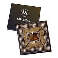
MCU HOST PROCESSOR 352-TBGA
Manufacturer
Freescale Semiconductor
Series
PowerQUICC IIr
Specifications of XPC8240LZU200E
Processor Type
MPC82xx PowerQUICC II 32-bit
Speed
200MHz
Voltage
2.5V
Mounting Type
Surface Mount
Package / Case
352-TBGA
Core Size
32 Bit
Program Memory Size
32KB
Cpu Speed
200MHz
Embedded Interface Type
I2C
Digital Ic Case Style
TBGA
No. Of Pins
352
Supply Voltage Range
2.5V To 2.75V
Rohs Compliant
No
Lead Free Status / RoHS Status
Contains lead / RoHS non-compliant
Features
-
Available stocks
Company
Part Number
Manufacturer
Quantity
Price
Company:

Part Number:
XPC8240LZU200E
Manufacturer:
MOTOLOLA
Quantity:
319
Company:
Part Number:
XPC8240LZU200E
Manufacturer:
Freescale Semiconductor
Quantity:
10 000
Part Number:
XPC8240LZU200E
Manufacturer:
FREESCALE
Quantity:
20 000


Electrical and Thermal Characteristics
Electrical and Thermal Characteristics
Table 12 provides the I
20
At recommended operating conditions (see Table 2) with LV
Notes:
1. Units for these specifications are in SDRAM_CLK units.
2. The actual values depend on the setting of the digital filter frequency sampling rate (DFFSR) bits in the frequency
3. Timing is relative to the sampling clock (not SCL).
4. FDR[x] refers to the frequency divider register I2CFDR bit n.
5. Input clock low and high periods in combination with the FDR value in the frequency divider register (I2CFDR)
20, 21
22, 23, 24, 25
0, 1
2, 3, 26, 27, 28, 29
4, 5
6, 7, 2A, 2B, 2C, 2D
8, 9
A, B, 2E, 2F, 30, 31
C, D
E, F, 32, 33, 34, 35
10, 11
12, 13, 36, 37, 38, 39 6144, 7168, 7680, 8192, 10240, 12288
Num
4
5
6
7
8
9
divider register I2CFDR. Therefore, the noted timings in this table are all relative to qualified signals. The qualified
SCL and SDA are delayed signals from what is seen in real time on the I
are delayed by the SDRAM_CLK clock times DFFSR times two plus one SDRAM_CLK clock. The resulting delay
value is added to the value in the table (where this note is referenced). See Figure 13.
determine the maximum I
FDR Hex
Data hold time
SCL/SDA fall time (from 2.4 to 0.5 V)
Clock high period (time needed to either receive
a data bit or generate a START or STOP)
Data setup time
Start condition setup time (for repeated start
condition only)
Stop condition setup time
2
Characteristic
160, 192
224, 256, 320, 384
288, 320
384, 448, 480, 512, 640, 768
576, 640
768, 896, 960, 1024, 1280, 1536
1152, 1280
1536, 1792, 1920, 2048, 2560, 3072
2304, 2560
3072, 3584, 3840, 4096, 5120, 6144
4608, 5120
MPC8240 Integrated Processor Hardware Specifications
2
C frequency divider register (I2CFDR) information for the MPC8240.
2
Table 12. MPC8240 Maximum I
C input frequency. See Table 12.
Freescale Semiconductor, Inc.
Table 11. I
For More Information On This Product,
Divider
Go to: www.freescale.com
2
C Input AC Timing Specifications
3
(Dec)
DD
= 3.3 V ± 0.3 V
2
C Input Frequency
Min
SDRAM_CLK
5.0
3.0
4.0
4.0
—
0
@ 33 MHz
1.13 MHz
2
C bus. The qualified SCL and SDA signals
733
540
428
302
234
160
122
83
62
42
31
Maximum I
SDRAM_CLK
2
@ 50 MHz
1.72 MHz
1.11 MHz
C Input Frequency
Max
—
—
—
—
—
1
649
354
819
458
243
185
125
95
64
48
CLKs
CLKs
CLKs
Unit
ms
ns
ns
SDRAM_CLK
@ 100 MHz
3.44 MHz
2.22 MHz
1.63 MHz
1.29 MHz
917
709
487
371
251
190
128
96
Notes
1, 2, 5
1
1, 2
1, 2
2
3
Related parts for XPC8240LZU200E
Image
Part Number
Description
Manufacturer
Datasheet
Request
R

Part Number:
Description:
Manufacturer:
Freescale Semiconductor, Inc
Datasheet:
Part Number:
Description:
Manufacturer:
Freescale Semiconductor, Inc
Datasheet:
Part Number:
Description:
Manufacturer:
Freescale Semiconductor, Inc
Datasheet:
Part Number:
Description:
Manufacturer:
Freescale Semiconductor, Inc
Datasheet:
Part Number:
Description:
Manufacturer:
Freescale Semiconductor, Inc
Datasheet:
Part Number:
Description:
Manufacturer:
Freescale Semiconductor, Inc
Datasheet:
Part Number:
Description:
Manufacturer:
Freescale Semiconductor, Inc
Datasheet:
Part Number:
Description:
Manufacturer:
Freescale Semiconductor, Inc
Datasheet:
Part Number:
Description:
Manufacturer:
Freescale Semiconductor, Inc
Datasheet:
Part Number:
Description:
Manufacturer:
Freescale Semiconductor, Inc
Datasheet:
Part Number:
Description:
Manufacturer:
Freescale Semiconductor, Inc
Datasheet:
Part Number:
Description:
Manufacturer:
Freescale Semiconductor, Inc
Datasheet:
Part Number:
Description:
Manufacturer:
Freescale Semiconductor, Inc
Datasheet:
Part Number:
Description:
Manufacturer:
Freescale Semiconductor, Inc
Datasheet:
Part Number:
Description:
Manufacturer:
Freescale Semiconductor, Inc
Datasheet: